Building a CAD Component
In this first section, we will build a 3D component. Engineers often use multiple types of analysis software to test their designs. This practice takes time; you need to learn each piece of software and compose a model for each one that will test for a parameter. However, OpenMETA tools allow you to run multiple types of analyses by composing just one model.
In the OpenMETA tools, we start a design by instantiating components and joining their interfaces, yielding a Component Assembly. We call this process composition. From this composed design, we can generate new models and run analyses.
First we must create a component for the Creo model we wish to test. This process breaks down into the following steps:
Creating a New OpenMETA Component
A component houses the Creo part reference, as well as defining objects for the Model. This is the smallest piece of the FEA TestBench hierarchy, so it must be developed first.
- In your GME Browser, open the RootFolder by left-clicking the plus box to the left of the name.
- Right-click the RootFolder and choose .
- Right-click the RootFolder and choose .
- Right-click the new Component folder and choose .
- Rename the component Simple_Cube.
- Double left-click Simple_Cube to open the blank component canvas.
- Located on the left is the Part Browser; left-click the Solid Modeling tab.
- Locate the Property object, left-click the image then drag and drop it onto the workspace.
Note
Make sure you’re using the Property object, not the Complex Metric.
- Click on the word “Property” and rename it PTC_Material_Name.
- Click the empy box in the Property and type ALUMINUM_ALLOY_6061_T6.
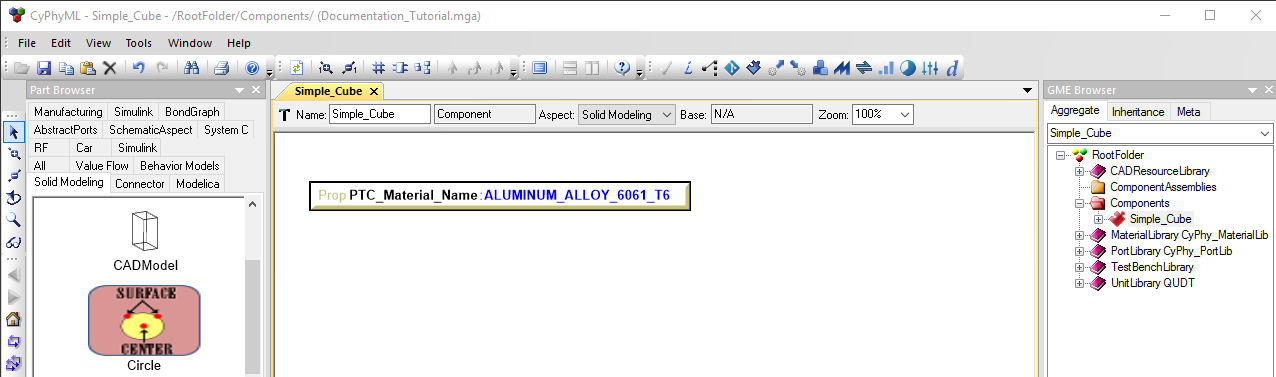
This will be used later when defining the material type for the mesher and solver software.
Reference the Creo Model
- Select the Component Authoring Tool
 from
the top tool bar.
from
the top tool bar. - Select the Add CAD tile.
- Navigate through and select the Creo versioned file creo_demo.prt.
Note
This process may take a few seconds as it converts the key features of the Creo Model into objects to be used by GME.
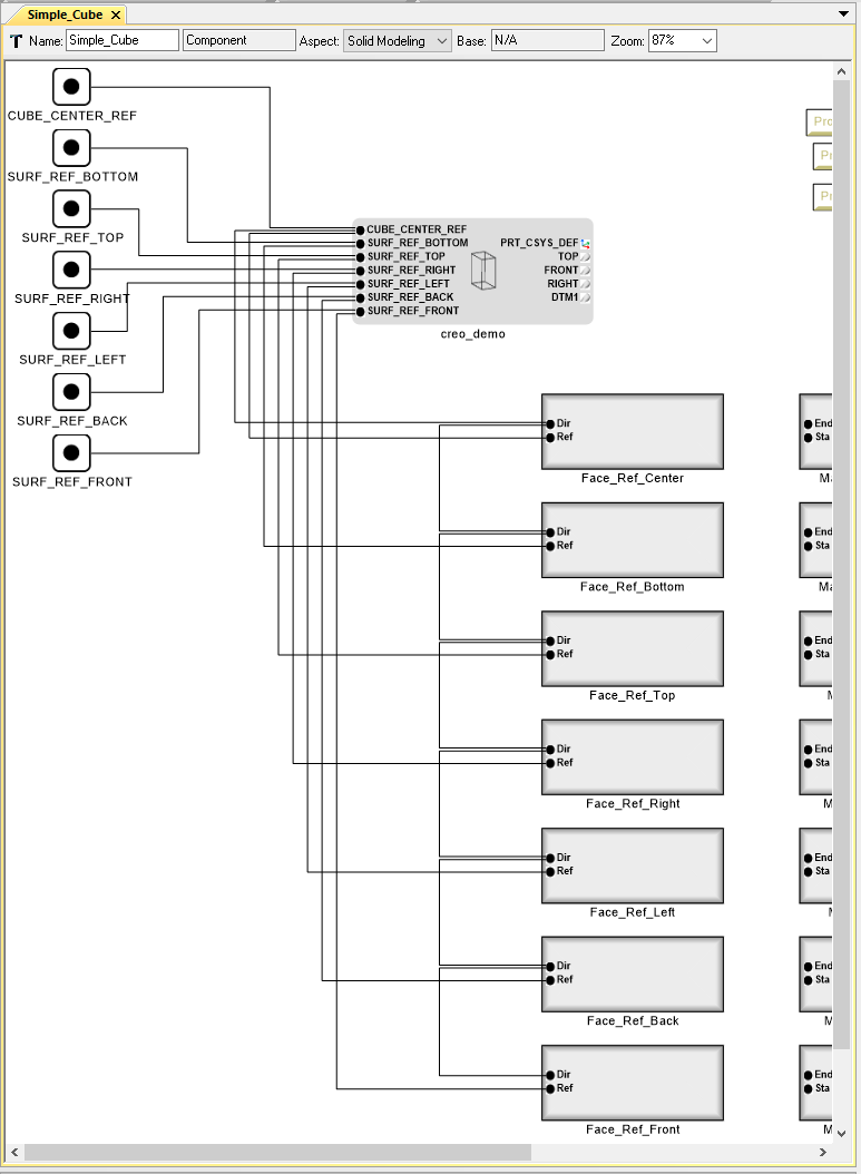
Now you should see a CADModel that is populated with CUBE_CENTER_REF, SURF_REF_BOTTOM, SURF_REF_TOP, SURF_REF_RIGHT, SURF_REF_LEFT, SURF_REF_BACK, and SURF_REF_FRONT. These are points on the center of every face of the cube in the Creo model.
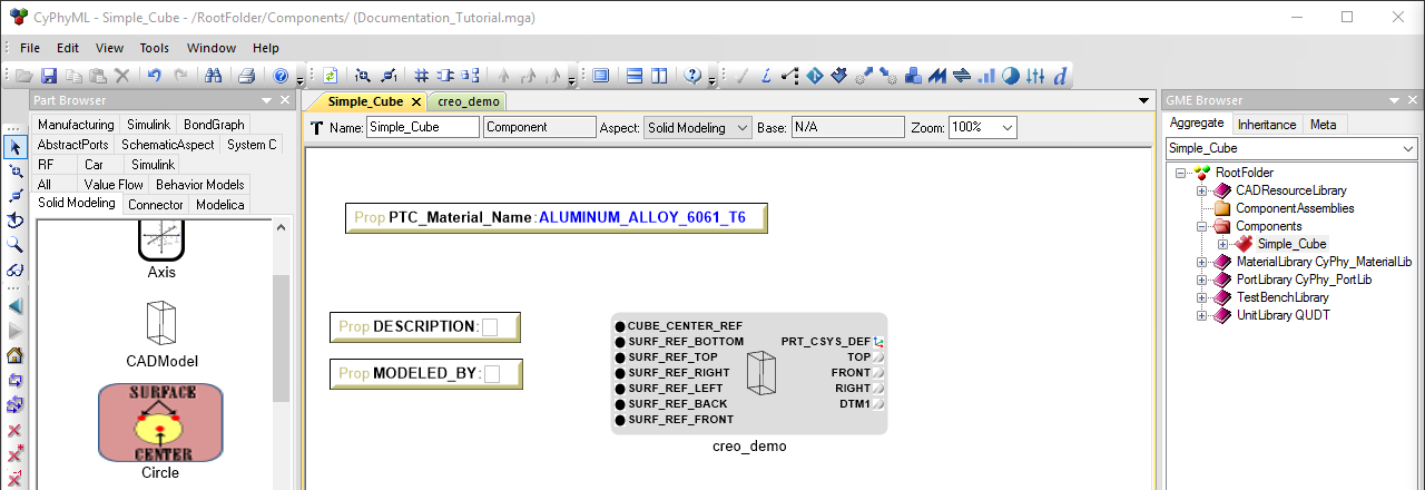
While they are defined in the model, they have not yet been defined in our component.
- Connect (Ctrl+2) the PTC_Material_Name to the Parameter with the matching
name in the CAD Model. (If this CAD Model Parameter is not visible,
make sure the canvas
Aspectis set to All.) - Select the Solid Modeling tab of the Part Browser.
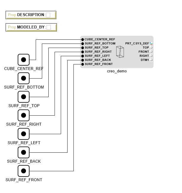
- Drag and drop the point object into the component workspace.
- Repeat this process 6 more times (one for every reference point on the model) and rename all points to match the names of the points in the CREO model.
- Enter connect mode (Ctrl+2) and connect all these points to their corresponding points as Port Composition in the CADModel.
Add Necessary Objects
We have now Exposed these points for future use. Next we need to add objects to help Patran, the meshing software, understand what is happening. Patran/Nastran need to know the normal directions of the faces used and the material orientation for each face as well. This is determined by the Face and Material Contents objects.
Face
- Drag and drop the Face object from the Solid Modeling tab of the Part Browser into the component workspace.
- Double click the Face object to edit it.
- Add one Direction_Reference_Point and one ReferencePoint (put the Direction point above the Reference point to make future steps more visible).
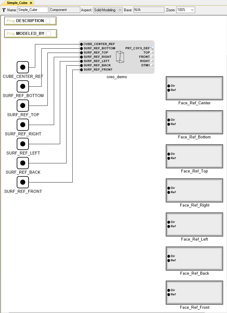
- Back in the Simple_Cube canvas, copy and paste 6 more of these edited faces (one for every point in the model)
- Rename these faces as “Face_Ref_Front, Face_Ref_Back, …”
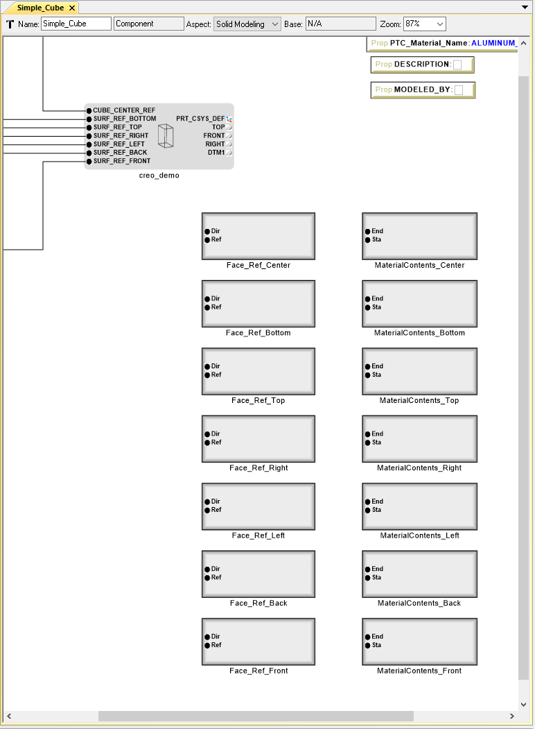
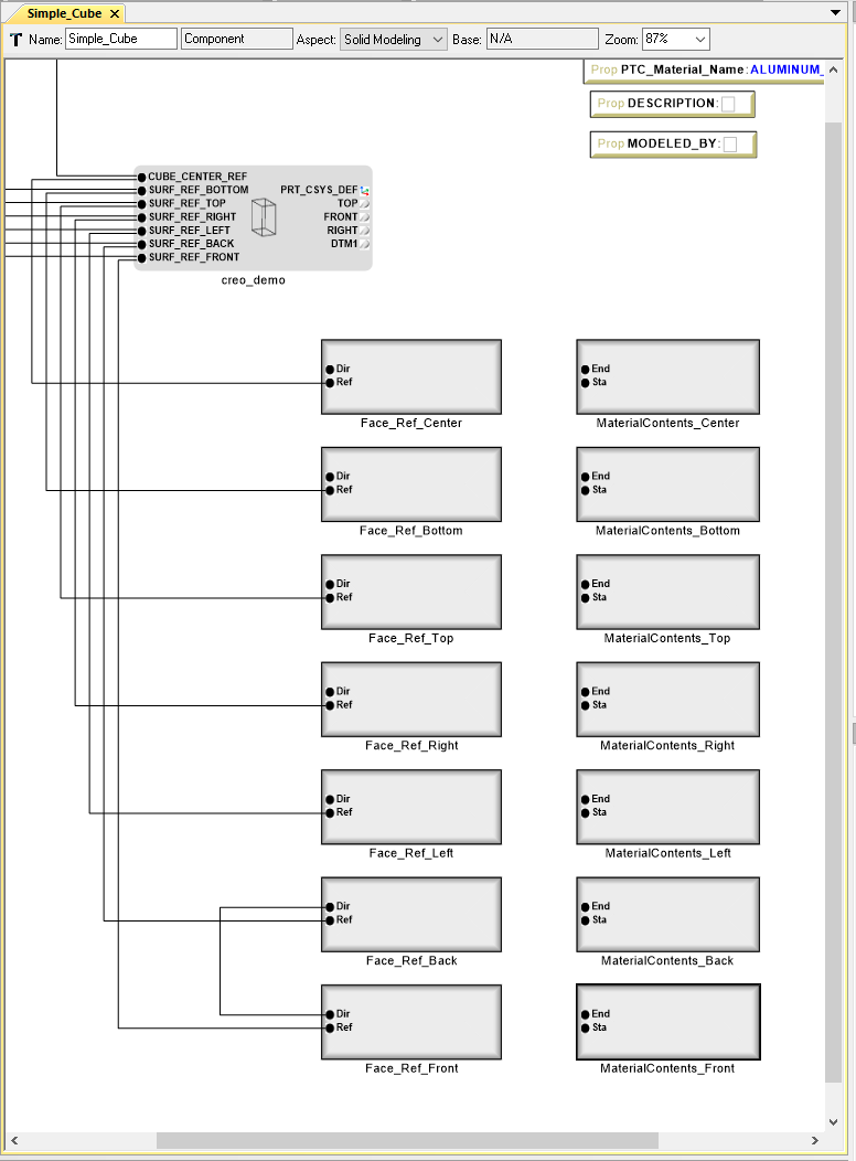
After completing these steps, your Simple_Cube component should be ordered similar to the following image.
Note
Descending order is important here as it will make later steps much more intuitive.
Material Contents
- Drag and drop the MaterialContents object from the Solid Modeling tab of the Part Browser into the component workspace.
- Double click the MaterialContents object to edit it.
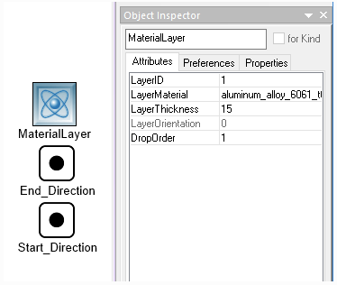
- Add the MaterialLayer, End_direction, and Start_Direction atoms aligned as shown below.
- Select the MaterialLayer atom, and click the Attributes tab in the Object Inspector on the left.
- Set all values as shown below.
- Back in the Simple_Cube canvas, copy and paste 6 more of these edited MaterialContents (one for every point in the model).
- Rename these faces as “MaterialContents_Front, MaterialContents_Back, … etc”.
After completing these steps, your component should be ordered like the following image.
Note
Descending order is important here as it will make later steps much more intuitive.
Making Connections
Now that we have all the necessary objects for the mesher and solver to fully define the model, we need to make the appropriate connections in our component. This can be done several ways, but the process described below produces the cleanest outcome.
Face Objects
- Enter into Connection mode (Ctrl+2), and connect the Reference_Point “Ref” of Face_Ref_Front to SURF_REF_FRONT exposed from the CADModel.
Note
All connections in the component building process will be port composition connections.
- Repeat this step for every Face Reference so that they all connect to the same name in the CADModel.
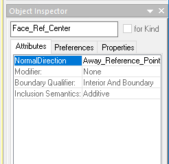
Note
Make sure that for all the faces, the Normal Direction option is listed as Away_Reference_point.
We have just assigned a reference to each face so that they connect to a real point in the model. Now we need to assign a direction for every point so that Patran/Nastran knows where the normal of each face points. We will need to use a point in the center of the cube so that every vector can be described as Normal Away From in the Object Inspector under the Attributes tab. You could just connect the DirectionReferencePoint of each face to the Cube_Center_Ref, but this would lead to a messy model with many connections. The cleanest way to do this is to Chain the DirectionReferencePoints together.
- Connect the Direction_Reference_Point “Dir” of Face_Ref_Front to Direction_Reference_Point “Dir” of Face_Ref_Back.
- Repeat this process from “Dir” to “Dir” ascending to the last “Face_Ref_…” object.
- Connect the Direction_Reference_Point “Dir” of Face_Ref_Center to Cube_Center_Ref on the CADModel.
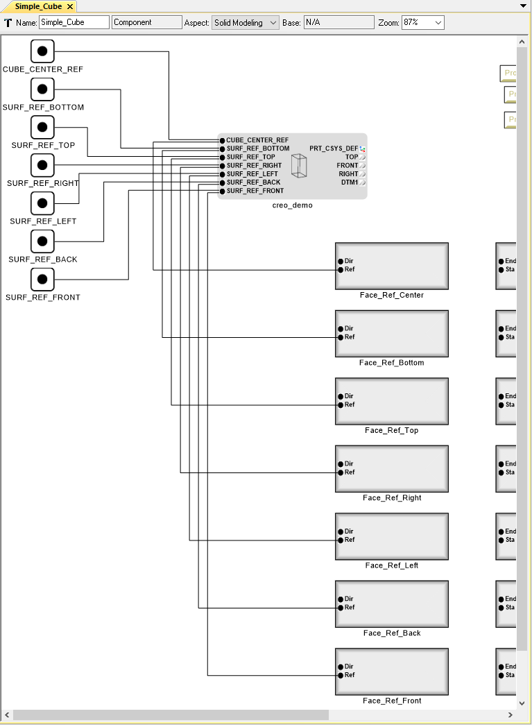
The Component should now look like this:
We have completed the face reference portion of the Component, so all that remains is connecting the MaterialContents.
Material Contents Objects
We will follow a lot of the same steps used to connect the Faces Objects but this process is slightly different.
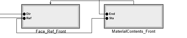
- Enter into Connection mode (Ctrl+2), and connect the Start Point “Sta” of MaterialContents_Front to ReferencePoint “Ref” of Face_Ref_Front.
- Connect the End Point “End” of MaterialContents_Front to Start Point “Sta” of MaterialContents_Back.
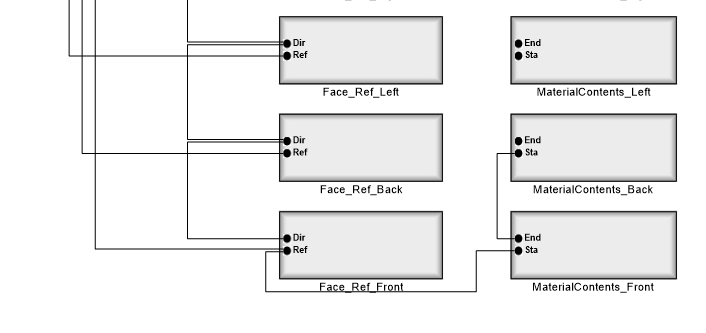
We have now Chained the MaterialContents_Front to both Face_Ref_Front and to MaterialContents_Back. Now MaterialContents_Front starts at Face_Ref_Front in the CADModel as shown by the Chain from MaterialContents_Front to Face_Ref_Front to SURF_REF_FRONT in the CADModel.
- Repeat step 2 for each material face so that they are connected as shown.
- Connect the End Point “End” of MaterialContents_Center to Cube_Center_Ref in the CADModel.
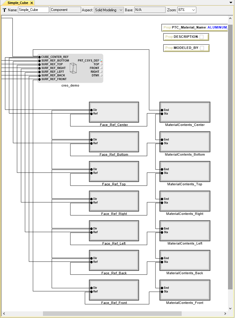
- Connect MaterialContents_Front to Face_Ref_Front.
- Repeat this step for each MaterialContents and its corresponding Face_Ref.
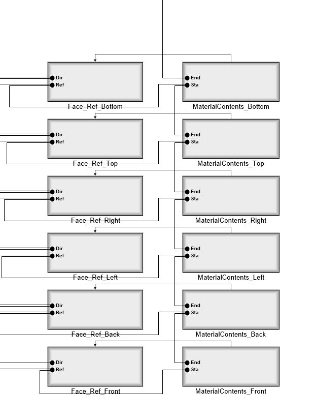
Now all of the MaterialContents objects are connected as needed. They reference the same point as their corresponding face object, and point in the direction of the previous Material Contents Object to the Cube_Center_Ref.