META Reference Guide
Parts, Ports & Connections
Parts List
Components & Assemblies
Components in META Tools represent everything we know about a component. META Models are multi-domain and contain schematics, CAD, behavioral and data-sheet components in one place. A user is able to leverage numerous analysis tools in one location, allowing the rapid consideration of multiple designs.

Component: an individual model in META.
This represents the physical and geometric simulation of an object so that it can be modeled in how it relates to other objects and/or its environment.
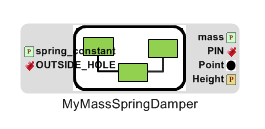
Example: The wheel of a car. This is only a single piece of what is assembled to create a whole car (see diagram of a component for image).
Component Assembly: a collection of models in META that interact with each other as a unit. This is the whole or a part of a whole which is created as components are assembled.
Example: The finished car or the entire powertrain of a car, both of which include several components to build.
Design Container: allows the user to contain variations of the same component to create multiple configurations.
Example: Use this to test many different combinations of engines, transmissions, and wheels in a car.
Properties, Parameters, and their Constraints
Properties and Parameters define the characteristics of the components and sometimes let the user specify some of their own.
Constraints put limits on properties and parameters in order to filter out too expensive, unwanted, or out-of-stock components from the possible range of designs. This range is called the Design Space, and the separate designs are configurations.
OR

Property: A value that is fixed and intrinsic for a given component. This can be added to an assembly to be able to access a component’s properties.
Example: The mass of a particular engine.
OR

Parameter: A value that can be varied within a range to define a component. Can be added to an assembly to specify certain values to a component to change its characteristics.
Example: How much gasoline a car starts with in a simulation.

Constraint: allows the user to create an expression to limit the options available for a configuration to reduce the number of possible configurations. This block allows the user to create a custom expression and paste it into the part’s object inspector under ‘constraint expression’.
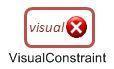
Visual Constraint: limits the options available for a configuration to reduce the number of possible configurations through operations, such as grouping compatible components that must be used together.
Example: In MSD, you would use a visual constraint to show that the steel mass has to go with the steel spring.
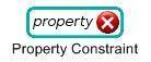
Property Constraint: limits the options available for a specific property to reduce the number of possible configurations.
Example: Property Constraints can be used to limit the overall height of a component.
TestBenches
Test Benching is the payoff for all the hard work in making a design in OpenMETA. A test bench will use Modelica, CAD, and other domains to simulate a design and provide useful and specific results. There are components which are special to tests called Test Components, which will wire into the assembly to simulate a testing environment or to collect data.
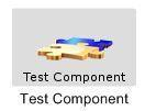
Test Component: A component that connects to the model to simulate forces and collect data for running tests. Test components sometimes require additional wiring to the assembly.
Component Assembly: Test benches can be run on just a component assembly, which will only test one configuration, the assembly.
Design Space Assembly: Test benches can also be run on a Design Space Assembly, which allows for multiple configurations to be tested.
OR

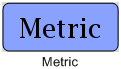
Metric: Used to collect specific data from a test subject so the user can later interpret and see these results.
Example: Connecting a Metric to the velocity output port of a car will record the car’s velocity during the simulation for later viewing.
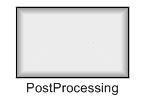
Post Processing: Processes data that is produced after a test is run using a specified Python script (.py file).
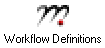
Workflow Definitions: tells OpenMETA which external simulator to use in the test bench.
Example: META2Modelica

Solver Settings: give the user control over simulation settings, such as the Solver, Test run time, and number of steps.
Example: Some simulation settings you have control over are start time, stop time, number of intervals, etc.
Connection Rules
- Connect only similar data types to each other. For example, signals connect to other signals and translational ports connect to other translational ports. Input and output ports may connect to each other.
- Not all ports necessarily need to have connections in an assembly. Some port inputs are provided by test benches, and some outputs are used for data retrieval during a test.
- If an arrow is not shown for a connection, the order in which the ports are connected is unimportant. This means directionality is not a concern when joining connectors, schematic pins, etc.
Assemblies
Component Assemblies
Component assemblies are similar to components, but are made up of several components and their connections. A component assembly can be opened by double-clicking on it in either the main editor window or the GME Browser.
When a component assembly is opened, the components it is comprised of and any ports for external interaction are visible. This makes component assemblies very useful for organizing larger projects into subsystems, or making a design more modular.
To create a new component assembly, in the GME Browser right-click the RootFolder, then select . Then right-click the ComponentAssemblies folder and select .
New Component Assembly
This new Component Assembly can now be opened by double clicking on it in the GME Browser, and components can be placed inside and connected. Any ports to connect to components outside of the assembly should also be placed here.
It is important that all of these ports are uniquely named to avoid confusion and errors. It is also very important not to use any spaces in the names of these ports, or you will get an error.
The overall arrangement of these ports will be preserved when outside of the component assembly. For example, see the figures below.
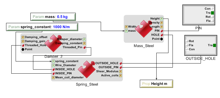
Figure 2.1.3
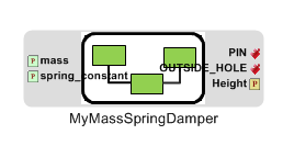
Figure 2.1.4
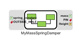
The ports are ordered vertically and horizontally on the outside based on how they are aligned inside the component assembly.
For example, the PIN is the top right port inside the component assembly, and it is also on the top right on the Assembly’s symbol.
If you find yourself in a position where you have several connected components within a component assembly and want to bring them out of the assembly while maintaining their connections, you can use the Design Space Refactorer tool (Figure 2.1.5).

Design Space Refactorer
Just select the assembly you want to extract, and click the Design Space Refactorer tool. A prompt will come up with several options. Choose extract the elements of Component Assembly.
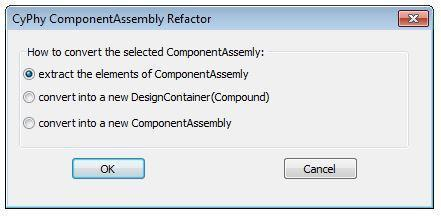
Figure 2.1.6
Design Containers
Design Containers are like folders that take the place of a component in a design; this design container contains all of the interchangeable components available.
First, make sure you have a design space by going to the top-level of your system and pushing the Design Refactorer tool as seen in Figure 2.2.1(with nothing selected in the main editor window). Then, select the component that you want to create a design container for and use the Design Refactorer again.
Design Refactorer Tool
A dialog box will appear. Select convert into a new Design Container (Compound) as shown in Figure 2.2.2.
New Design Container (Compound)
This will convert the component into a design container. After being converted, the container should look like the image shown in Figure 2.2.3
Design Container
Double click on the container to open it. Here, new alternative components can be connected manually or automatically. If you wish to do it manually, simply copy the alternative component(s) and paste it as reference(s).
Once this is done, connect the new component(s) the same way the original one was connected. To automatically make connection, just click the CLM_Light tool (Figure 2.2.4).

CML_Light tool.
This will bring up a dialog box (Figure 2.2.5). Select all (Ctrl-A) the components you wish to automatically add, then click “Ok”.
Adding Components
To test the number of possible combinations in your design, refer to section VI of this document.
Toolbars
Mode Toolbar
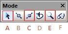
A. Edit Mode - Shortcut: (Ctrl-1)
- Single-clicking an object in the workspace allows the user to view further information on the selected object in the Object Inspector.
- Using the arrow keys or mouse, the user may move the selected object(s) around.
- Object 1 can be placed inside of Object 2 by dragging Object 1 above Object 2.
- Single-clicking a wire in the workspace will highlight the wire to better show the ports in which the wire is connected.
- Once a wire has been selected in Edit mode, the user may click and drag segments of the wire for organizational purposes.
- Double-clicking an object opens up a new workspace showing the contents of that object.
B. Connect Mode - Shortcut: (Ctrl-2)
- Connect Mode allows the user to manually wire two ports together by selecting each of the two ports to be wired together.
- With the exception of certain instances, the order in which two ports are connected generally doesn’t matter.
- Some ports allow multiple connections while others only accept 1:1 (Check the specific port description for more info)
C. Disconnect Mode - Shortcut: (Ctrl-3)
- Single-clicking a wire in disconnect mode will delete the wire, and thus, the connection between the two ports it was attached to.
D. Set Mode - Shortcut: (Ctrl-4)
E. Zoom Mode - Shortcut: (Ctrl-5)
- In this mode a user can toggle how far zoomed in/out their window is.
- Each left click zooms the user in about 25% while each right click zooms the user out by about 25%
- As a shortcut to this tool, the user can hold “Ctrl” and scroll up and down to zoom in and out
F. Visualization Mode - Shortcut: (Ctrl-6)
- Upon selecting this mode, every object and wire in the workspace are grayed-out.
- By selecting two objects in this mode, the user can easily view all connections between the two objects.
Modeling Toolbar
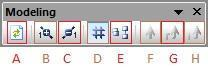
A. Repaint: Refreshes the current work space.
B. Non-Sticky Connect Mode: Allows user to make one connection at a time. After making the connection, it returns to edit mode.
C. Non-Sticky Disconnect Mode: Allows user to disconnect one connection at a time. After disconnecting, it returns to edit mode.
D. Grid:: Displays a grid in the background of the workspace.
E. Synchronize aspects: Use this tool to apply the layout of the current aspect to all other aspects.
F. Parent: If inside a nested assembly, returns to higher level assembly.
G. Show Basetype
H. Show Type
Navigator Toolbar
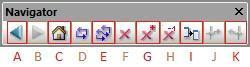
A. Back: Brings up the last model that was in the workspace. (Analogous to going back a page on a web browser.)
B. Forward: Brings up the next model visited if you have already used the Back button at some point. (Analogous to going forward a page on a web browser.)
C. Home: Selects the highest level open model and brings its workspace to the front.
D. Cycle Aspects: Changes aspect mode to the next aspect mode in the list for the selected model.
E. Cycle Aspects For All Open Models: Changes aspect mode to the next aspect mode in the list for all open models.
F. Close Model: Closes out of the workspace for the currently selected model.
G. Close All Models: Closes out of all of the workspaces for all of the models currently open.
H. Close All But Active Model: Closes out of all of the workspaces except for the one currently being viewed.
I. Next Window: Cycles through the currently open workspaces in the order they were opened.
J. Jump Along outgoing connection: If a component is selected, a window will appear showing the user where each of its connections are coming from.
K. Jump Along incoming connection: If an independent port is selected, a window will appear showing the user where each of its connections are going to.
Windows Toolbar
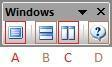
A. Full Screen: Brings the main editing window into a full screen view. (Useful for viewing large, complex assemblies.)
B. New Horizontal Tab Group: Splits the main editing window into two horizontal rows. (Useful for comparing two systems or simultaneously viewing different aspects.)
C. New Vertical Tab Group: Splits the main editing window into two vertical columns. (Useful for comparing two systems or simultaneously viewing different aspects.)
D. About: Displays GME information, such as version number, copyright information, etc.
Constraints
There are multiple uses of constraints, but their main use is to limit the options available and thus reduce the number of possible configurations. This limitation is necessary because some components are compatible only with certain other components. For example, installing a special type of shocks in a car’s suspension may limit the number of different A-arms that can be used in the suspension. This situation represents a constraint that has been put on the design space.
Visual Constraints
To add a constraint you must be in the ‘Design Space’ aspect view of your Design Space assembly. In the Part Browser, find the VisualConstraint icon and drag it into the workspace.
To state that two or more components are only compatible with each other, you will copy each component and paste it as a reference within the visual constraint.
Then you will enable the connection tool, click in the center of each component to create a directional connection to no particular port.
Do this again to create a connection in the opposing direction. The final connections within your visual constraint should resemble the figure below.
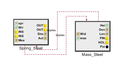
Connections
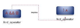
If you would like to create a constraint that specifies two components which should not be used together within the same configuration you must use a Not_operator within the visual constraint.
To do this, create and open a visual constraint, drag in a Not_operator. Next, you will copy the components which are not to be used together and paste them as reference within the Not_operator.
Property Constraints
This constraint can be used to limit possible values for properties such as “Height” from the MSD tutorial.
The MSD tutorial uses a height property which allows the system to define the measured height of the Mass.
A property such as this can be limited by dragging in a property constraint and connecting it to the property it will be affecting.
Next, you will specify the nature of the constraint by selecting the property then referring to the object inspector where the attributes can be changed to limit the property as needed. For additional aid see Figure 4.2.1 below.
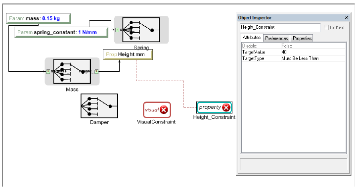
Adding Property Constraints
Parameter Constraint
The individual components of an assembly have physical limitations - for example, a spring can only stretch so far. These limitations are also a part of the simulated assembly in the form of parameter constraints.
Each model has a set of values for certain properties and parameters. The Parameter constraint is assigned a range of acceptable values, and it will reject any component whose values lie outside of that range.
This keeps configurations that use those components from being simulated. You can assign a range to a Parameter constraint by selecting the constraint block and then going to the Object Inspector and changing the value in the box labeled “Range”.
For the MSD tutorial, we wanted to make sure that the constraint block deals with the range values of the individual alternate components that we just added. If the Parameter blocks affecting those components have assigned range values, those values risk overriding the values of the individual components.
To avoid overriding the range values in the components, we will need to make sure that the Parameter blocks connected to the components do not have a range value.
To do this, select one of the Parameter blocks in the design space and delete the range value.
Do this for all of the Parameter blocks which have range values within the components. This must also be done for the Parameter and Property blocks of individual components. See Figure 4.3.1 below.
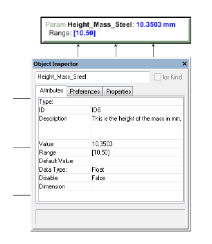
Defining Parameters
Advanced Constraints
More advanced constraints can be constructed through combinations of ‘And_operators’ and ‘Not_operators’. And_operators may be used to specify a condition for a constraint as the use of two components together. A not_operator is a constraint which specifically targets a component, or several which cannot be included in the configurations given a condition.
For example, you may wish to specify that when two components are used together, another component should not be included within the same configuration.
To do this, you would paste the two components, which will be used together in this condition, as reference into an ‘And_operator’ then connect the operator to a ‘Not_operator’ which will include the component(s) which will be excluded given the defined condition. This can be seen in Figure 4.4.1.
‘And_operator’ and ‘Not_operator’
Debugging
Double Checking Everything
Many times a small error on the user’s part can be the source of all kinds of problems. If a user finds their test bench to be producing many errors, it is recommended that they run through this checklist to ensure that no small details have been overlooked:
- Ensure that no object within the workspace has the same name.
- Ensure that no components or ports have names that contain spaces.
- Check to see if everything that needs a connection has a connection.
- Make sure Structural Interface Ports do not have multiple connections.
- Make sure that each test component is properly connected to the correct port(s).
- If there are parameters in the test bench, make sure they are properly defined and wired in the correct order (parameter to port).
- Be sure that the metric(s) of your output(s) is/are defined and wired in the correct order (port to metric).
Viewing Errors
The Console
While running the OpenMETA Master Interpreter, status messages will appear in the GME Console. These messages have different types such as Info, Warning, Error, Success, and Failed.
Common Error Messages
| Error | Solution |
|---|---|
| Failed execution | Check console for details |
| Property/Parameter: ________ cannot have more than one source ValueFlow. OR ____ VF’s > 1 | Make sure that all your arrows going to and from all your properties and parameters are going in the right direction. This error usually means that a property or parameter is getting its value from two different places. |
| Errored Constraint No: 1———- Constraint Set: constraints Constraint: VisualConstraint Context: MyMassSpringDamper Context Error: ClFunction::Children : child not found Exception: ClRelExpr:: Eval(ClContext& c, const CCosmic left, const CCosmic right): At least one of the operands does not exist! | The error is caused by copying the files from the imported components and not the design space |
| Queued Local | Seems to be a bug in the Master Interpreter, just rerun the test bench while keeping the JobManager open and it should work |
| This interpreter can be used in 3 different modes. This is none of the following. | Complete “Double Checking Everything” section |
| Object handle null | Complete “Double Checking Everything” section |
| Invalid Test Bench Structure | There may be an extra piece in your test bench, check console for details |
| Syntax Error | Check that the names of files within folders do not have any spaces |
| _____ not found in the scope | Make sure that all the libraries that need to be included are. |
| ______ already declared in scope | This means that two or more ports or components have the same name. Make sure that each port has a unique name. |
| Model is structurally singular | Check your connections again (esp. translational power ports). |
| ValueFlow error: m and the incoming ValueFlowTargets’ unit dimensions are not compatible! | Review the units on all Parameters and the arrows connecting them. |
Interpreting the Error Log
Often times the error log is full of useless information to the user. It may contain various misleading errors and redundant warnings that in no way help the debugging process.
Fortunately, however, there are times that the error log can be useful if one knows how to correctly interpret it. The following are examples of how the user might be able to debug their assembly based on error log messages:
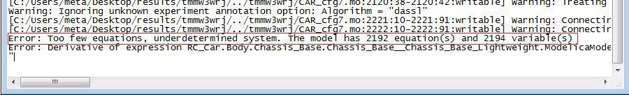
Too few equations error.