SPICE Circuit Simulation
SPICE (Simulation Program with Integrated Circuit Emphasis) is a time-tested simulation tool for electronic circuits. NGSPICE is an open-source version that is used by and included with the OpenMETA tools.
NGSPICE Models
OpenMETA components can use NGSPICE models to represent their electrical behavior. They can do this by either parameterizing common SPICE primitives or by providing their own implementations in standalone files.
Modeling Guidelines
Purpose and Scope
The CyPhy modeling environment uses SPICE model files to perform electrical simulations of user-defined component assemblies. This subchapter describes how to obtain SPICE model files for electronic components and how to add SPICE model files to CyPhy component definitions. Its intended audience is mainly ARA module designers who will be adding custom electronic component models to the CyPhy modeling environment.
Note
This subchapter does not describe how to actually run CyPhy SPICE simulations of component assemblies; for more information on running these simulations, see Project Ara Test Benches.
How SPICE Models are used by CyPhy
SPICE has evolved into many varieties, some of which are proprietary and encrypt the SPICE model files. The flavor of SPICE the CyPhy modeling environment uses is an open-source version called “NGSPICE” that uses clear-text model files.
The main reference for NGSPICE, the NGSPICE User Manual Version 26plus, is available at: http://ngspice.sourceforge.net/docs/ngspice-manual.pdf
NGSPICE model files typically have the file-name extension “.cir”, and are referred to in this subchapter as CIR files. A CIR file is just an ASCII text file, so it can be viewed and edited with text editors.
Figure 1 helps to explain the progression of SPICE-model information within the CyPhy modeling environment.
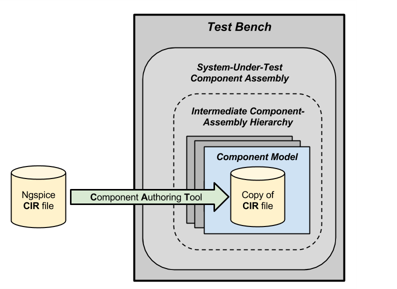
Figure 1: Simplified overview of the progression of SPICE-model information
The items in Figure 1 of most relevance to this subchapter are shaded yellow, green, or blue, and the items of lesser relevance are gray.
The most relevant items are explained as follows:
- On the left is a yellow NGSPICE CIR file, that will be used as input to the Component Authoring Tool (CAT). This CIR file may have been obtained from a component manufacturer, copied from a library of SPICE model files, or generated by the user based on data-sheet information.
- The green arrow represents the CAT, which is used, among other things, to copy a SPICE model file into a directory associated with a Component Model. Additional details about using the CAT to add a SPICE model to a component are described later in a section titled, “Adding a SPICE model using CAT”.
- The blue rectangle in Figure 1 represents a component model.
- The yellow “Copy of CIR file” in the blue component model represents a copy of the NGSPICE CIR file on the left. This copy was made by the CAT during component creation, and is physically stored with the component-model’s archetype.
The gray items are described briefly below:
- The dark-gray rectangles behind the blue component model represent some number of additional component models. Some might be references to the blue component’s archetype, and thus share the same CIR file as the blue component.
- The dashed rounded rectangle labeled “Intermediate Component-Assembly Hierarchy” serves as a reminder that there could be multiple levels of nested component assemblies in the system under test, each of which could contain multiple component models or other component assemblies.
- The “System Under Test” component assembly represents the top level component assembly of the system being tested.
- The large outer rectangle labeled “Test Bench” represents the CyPhy test bench used for SPICE electrical-behavior simulation.
When the SPICE-model interpreter is run from the test bench, it generates a composite CIR file based on the CIR files associated with the component models within the system under test, based on the CyPhy model’s connections. The generated composite CIR file is then run through SPICE, to simulate the system-under-test’s electrical behavior.
Theoretically, if all the SPICE component models in a system have an appropriate CIR file, then this allows for the electrical simulation of the complete system. Otherwise, a more focused divide-and-conquer strategy may be appropriate. Practical difficulties of modeling a complete design include:
- All components may not have open-source SPICE models available.
- Detailed SPICE models can take a long time to run.
Obtaining or creating SPICE models with the right level of fidelity for a given purpose still requires skill and effort.
Additional SPICE tools
Users working with CIR files may find the following tools helpful:
- LTspice IV is a proprietary but free SPICE simulator available from Linear Technology, that appears to be compatible with NGSPICE models, that can be downloaded from here: http://www.linear.com/designtools/software/#LTspice
- “NGSPICE Online” is a website that lets you run NGSPICE models. Here’s a link: http://www.ngspice.com/
Where to obtain SPICE models
In general, the best source of SPICE models for a component is the component’s manufacturer. Manufacturers of passive devices and discrete semiconductors often make open-source SPICE models available that, with little or no effort, can become NGSPICE compatible. Here’s a web page with links to manufacturers’ SPICE-model download pages: http://www.5spice.com/links.htm
If a manufacturer-supplied open-source model is not available, there are still several possibilities, listed here in no particular order:
- an open SPICE model for the component, created by someone other than the manufacturer, might be available online,
- a SPICE model for an electrically similar component might be substituted,
- a simple SPICE model might be approximated from the component’s datasheet specs,
- a SPICE model might be developed from measured component characteristics.
Required and recommended features of CIR files
One convention used by the CyPhy tools while adding CIR files to components is that the first “.SUBCKT” subcircuit or “.MODEL” device model found in the CIR file will be used as the CyPhy component’s SPICE model. So, CIR files must contain a subcircuit or a model.
If you are in doubt about whether to start the non-comment portion of the CIR file with a “.SUBCKT” or a “.MODEL” definition, use a “.SUBCKT”. It provides more functionality than a “.MODEL” definition, and also better pin-name documentation.
CIR files should not contain multiple “.SUBCKT” statements, since only the first one is recognized.
Furthermore, only a subset of the full NGSPICE language is supported. Specifically, the following NGSPICE language constructs are not permitted:
Subcircuit parameter values consisting of brace expressions.
“.PARAMS” and “.FUNC” statements.
The following element types, from Table 2.1 on page 46 of the NGSPICE Users Manual Version 26plus:
- ‘A’ – XSPICE code model
- ‘K’ – Coupled (Mutual) Inductors
- ‘N’ – Numerical device for GSS
- ‘P’ – Coupled multi-conductor line (CPL)
- ‘X’ – Subcircuit
Sample CIR files
A Capacitor using a “.SUBCKT”
Figure 2 shows a CIR file for a 0.1uF capacitor in an 01005 package, with its text printed black. The line numbers on the left are not part of the CIR file, but were just added for reference. Lines 1-7 are a comment which would be ignored when parsing the CIR file. Line 8 is the first “.SUBCKT” statement, and starts the definition of an equivalent circuit for the capacitor, which extends to the “.ENDS” statement on line 13.
The NGSPICE Users Manual describes the syntax and semantics of these SPICE statements. Also, an equivalent circuit for this capacitor model is shown in Figure 3 below.
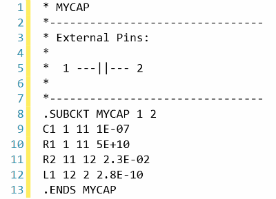
Figure 2: Capacitor CIR File
As seen on lines 5 and 8 of Figure 2, and shaded blue in Figure 3, this capacitor model has two SPICE pins visible outside the subcircuit, named “1” and “2”.
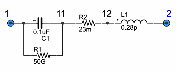
Figure 3: Capacitor Equivalent Circuit
The equivalent circuit shown in Figure 3 includes both an ideal capacitor and three parasitic elements, as follows:
- C1 is the ideal capacitor.
- R1 is the leakage resistance.
- R2 is an equivalent series resistance.
- L1 is the lead inductance.
Other equivalent circuits for this capacitor with varying numbers of parasitic elements and degrees of accuracy are also possible; however, exploring model-accuracy tradeoffs is beyond the scope of this subchapter.
A 2N222A using a “.MODEL” statement
A CIR file with a “.MODEL” statement instead of a “.SUBCKT” statement as the first non-comment statement is shown in Figure 4.
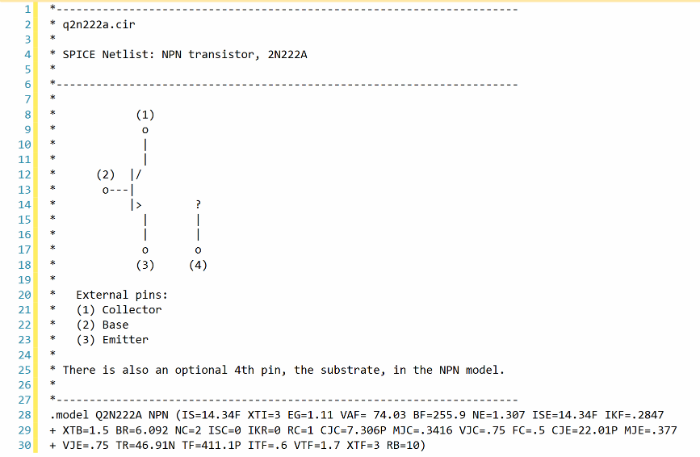
Figure 4: CIR file starting with a “.MODEL” statement
Although the comment lines in Figure 4 give some clues, the “.MODEL” statement in lines 28-30 doesn’t document the component’s SPICE pins. Also, the equivalent circuit described by this CIR file can’t be expanded to include other elements, such as lead inductance, without starting the CIR file with a “.SUBCKT” statement.
An Si8808DB N-Channel MOSFET
A CIR file using an initial “.SUBCKT” containing multiple “.MODEL” definitions, is shown in Figure 5. This CIR file models the Vishay Siliconix Si8808DB N-Channel MOSFET.
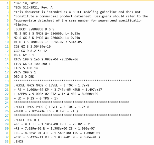
Figure 5: A MOSFET CIR file using “.SUBCKT” and “.MODEL” definitions
Although at first glance Figure 5 looks like a valid NGSPICE file, it is actually for a different variety of SPICE. If LTspice IV were used to check this CIR file, it would identify some problems. For instance, R1 on line 10 of Figure 5 has multiple position-determined parameter values. However, NGSPICE’s resistor model only has two pin names and a resistance value as positional parameters; other parameters such as optional temperature coefficients would need to be indicated by keyword=value pairs.
Adding a SPICE model using CAT
The best way to add a SPICE model to a CyPhy component is to use the Component Authoring Tool (CAT), similar to how it was used previously in the Electronic Design Automation (EDA) section to add the EDAModel to the CyPhy component.
The Canvas after adding a CIR file
Figure 6 shows a component’s canvas after a CIR file has been added to the component via CAT, with blue numbers added to help identify items of interest.
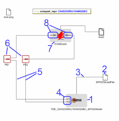
Figure 6: Component with SPICE model added
The blue-numbered items shown in Figure 6 are explained as follows:
- This is the SpiceModel model that CAT added to the component.
- This is the SPICEModelFile resource that CAT added. It contains a path attribute that links to the CIR file.
- This is the connection between the SPICEModelFile resource and the SpiceModel model.
- These are the SpiceModel pins. They are two SchematicModelPort pins that CAT added to the SpiceModel, based on two SPICE-model pins CAT found while parsing the CIR file. The names of these pins come from the “.SUBCKT” statement of the CIR file; or for CIR files that use an initial model, the pin names come from a model-based table of default pin names coded within CAT.
- These are the connections CAT added between the SpiceModel pins and the component pins.
- These are the component’s pins, which correspond to EDAModel pins. They were created when the EDAModel was added to the component, prior to adding the SPICE file.
- This is the EDAModel, which encapsulates schematic and PCB footprint information.
- These are the pins of the EDAModel. They were connected to the component’s pins prior to adding the CIR file.
Automatic Pin-Name Matching
CAT attempts to automatically connect the SpiceModel pins to the correct component pins, based on comparing the names of the SPICE pins and the component pins. This works pretty well as long as the pin names are reasonably close. For instance, in Figure 6, the SPICEModel pin named “1” was connected to component pin named “P$1”, and SPICEModel pin “2” was connected to component pin “P$2”.
If needed, the user can also manually create or change the pin connections within the CyPhy component model. For instance, if the circuit designer wanted SPICE pin 1 connected to component pin “P$2”, they could manually make that change. To avoid the need for this extra step, however, it’s best to choose SPICE pin names that are similar to the component pin names, which (unless modified) are the schematic pin names.
To help circuit designers verify that their SPICE pins have automatically been connected correctly, CAT produces console messages such as:
Running Component Authoring interpreter.
Created a new SPICEModel: "TDK\_C0402X5R0J104M020BC\_SPICEModel"
Connecting SPICE model pin "1" to component pin "P$1".
Connecting SPICE model pin "2" to component pin "P$2".
Copied file "C:\Users\Meta\Desktop\MyComponents\Library\C\_01005\_0.1uF\spice\C\_01005\_0.1uF.cir"
to "C:\Users\Meta\repos\tonkalib\authoring\_models\nklabs\_ara\_proto\_board\components\deavgwwp\Spice\C\_01005\_0.1uF.cir".
This listing confirms that CAT connected the SPICE pins as shown in item 5 of Figure 6.