Components
The component is the atomic model construct in OpenMETA, and it serves as the basis for the multi-domain nature of the tools. Components touch virtually every other concept in OpenMETA.
What’s Inside a Component Model?
Inside a component, you will typically see one or more domain models and a number of interfaces exposing parts of the component to the containing environment. For example, you could have a schematic model, CAD model, and Modelica model, along with many properties, connectors, and other essential parts. The component model captures several qualities of the physical component, including its geometry (3-dimensional CAD model), its dynamic behavior (an acausal power flow and transfer function), and its numerical properties (characteristics such as weight). The component also has connectors, which allow connection to other components.
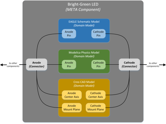
Concept drawing of an OpenMETA Component Model of an LED
The OpenMETA Component Model aggregates these various models, providing a single set of properties and connectors. When two components are composed via these connectors, they are joined in many analysis domains at once.
The figure below shows a simple capacitor component as represented in OpenMETA.
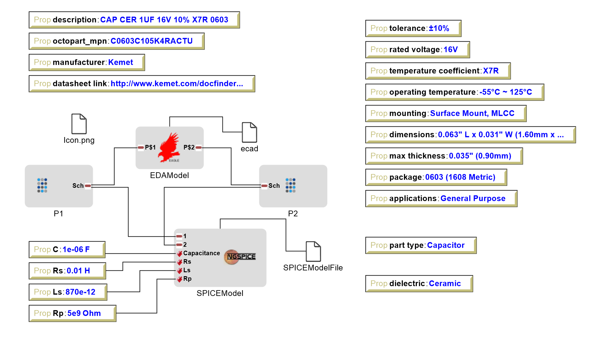
OpenMETA Component Model of a Capacitor
Domain-Specific Models
For each of the domains represented in the component model, there is a domain-specific model that exposes the necessary features of that domain.
For example, in the OpenMETA Component Model of a Capacitor figure above we see that this capacitor has both an EDA and a SPICE model. The EDA model exposes the two pins which represent the phyiscal pads of the part footprint on a printed circuit board (PCB) to which other components need to connect. The SPICE model also exposes the two pins of the component but additionally exposes four values needed to construct an accurate representation of the capacitor in the SPICE domain. The properties that specify the appropriate values for the SPICE model as well as a number of other properties that describe this component are described in the next subsection.
Properties & Parameters
Components will typically contain a number of different properties and parameters. Properties and parameters are ways of capturing values that describe components. Properties are values that are fixed for a given component and cannot be changed directly by a designer using that component. Parameters are values that can be varied by a system designer. For example, in the case of a drive shaft where the designer can have one manufactured to a custom length, the component model for that drive shaft will have length as a parameter.
A property may also be calculated automatically based on the values of other properties or parameters. In the example of a drive shaft, the mass of the drive shaft is calculated from the length.
This extends to the domain models as well. Again in the case of the drive shaft example, the user-selected length can be assigned to a parameter of the CAD model, adjusting the 3D geometry based on the designer’s selection. The calculated mass can be assigned to a parameter of the dynamics model, ensuring that the correct inertia is used when simulating its behavior.
Note
Insert an image of the drive train component.
Connectors
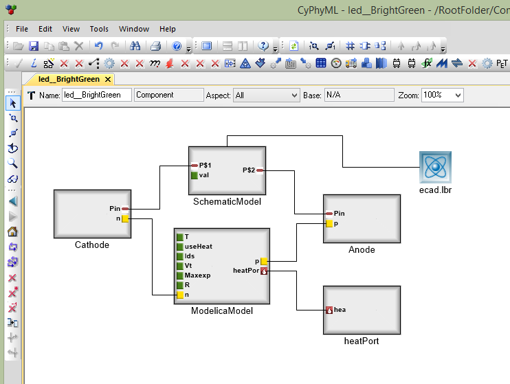
OpenMETA components also contain connectors, which define interfaces across multiple domain models. For the case of an electrical pin connecting to a printed circuit board (PCB), the joining of two connectors can capture the geometry (the center axis and mount plane where the pin and board meet) and the schematic diagram relation (which pins/nets are being joined) at the same time.
In the screenshot below, the connector Cathode represents both an electrical terminal from the SchematicModel and an electrical interface from the ModelicaModel.
Note
We need to update this image to include the new Connector look.
The simplified diagram below abstractly shows the structure of a similar component, with its individual domain-specific interfaces grouped into connectors. For more information on how Connectors are used to compose OpenMETA Components, visit the Component Composition section of the next chapter.
Concept drawing of an OpenMETA Component Model of an LED
Managing Complexity
As the size and complexity of a project grow, the number of components and difficulty of maintaining them also increase. To ease the task of component management, OpenMETA supports component references, component instantiation, and component class inheritance.
Component References
The most common approach for sharing component libraries is to create or import OpenMETA Components from a library and to use references of those components in the Component Assemblies and Design Containers used to express your design. This allows us to use the exact same component in multiple places.
To instantiate a Component into an open Component Assembly or Design Container, right-click and drag the Component from the GME Browser onto the canvas. When prompted, select Create Reference. For an example of this technique, see Adding a Component Assemblies Folder.
Although components can also be copied or created directly within Component Assemblies and Design Containers, we recommend keeping all the components in the project confined to Components Folders and using component references everywhere components are used.
Object Instantiation
Components can also be added to Component Assemblies and Design Spaces as instances, but this is not recommended. As instances, they behave similarly to components that are referenced, but are at times incompatible with the various interpreters.
Instead, instances should be used when you want to have a single definition for an object and use it multiple times but the context precludes using references. For example, you will often have a number of components that share a common connector interface. It is useful to create a connector definition and then simply instantiate that connector in all the components that need it. If later it becomes necessary to add an additional domain to that interface, you only have to do so once in the definition and it will be replicated in all instances of that connector.
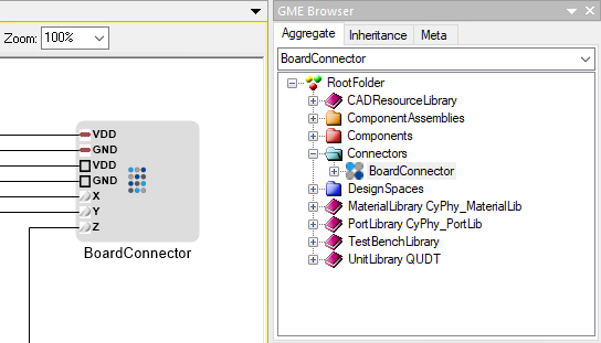
Electronics Connector with Physical, Electrical, and Dynamics Domain Ports
Class Inheritance
Components can be created as subclasses of other Components. This is useful for building and managing large libraries of Components that share many of the same characteristics. When model objects are added to the base class components, they are automatically added to the derived component classes.
To use Class Inheritance to streamline Component Authoring, let’s revisit the Adding Team Members section of the Hello World tutorial. In the tutorial, we created four team members. Even though each team member was different, they shared many Properties in common. We will use Class Inheritance to make managing these Properties more efficient.
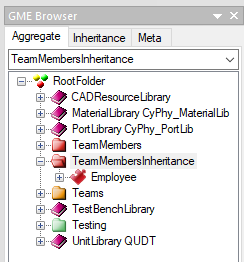
Right-click on the RootFolder, and choose .
Rename this new Components folder TeamMembersInheritance.
Right-click on the new TeamMembersInheritance folder and choose .
Rename this component to Employee.
We will treat this Employee component as a baseclass, and use subtyping to derive specific team members from it.
Right-click on Employee and choose .
Right-click on the TeamMembersInheritance folder and choose .
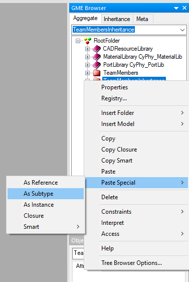
You will see a new Employee Component which includes a small “s” next to its icon.
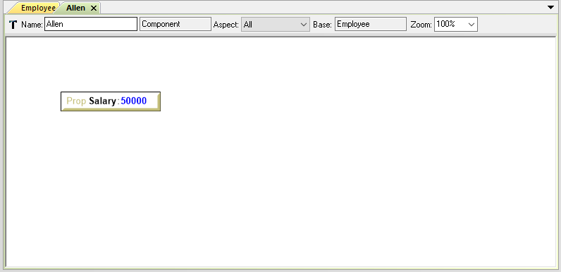
Rename this Component to Allen.
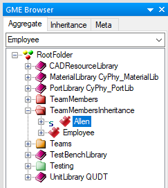
The Allen Component inherits from the Employee component. If we add Properties or other fields to Employee, they will be created within Allen as well.
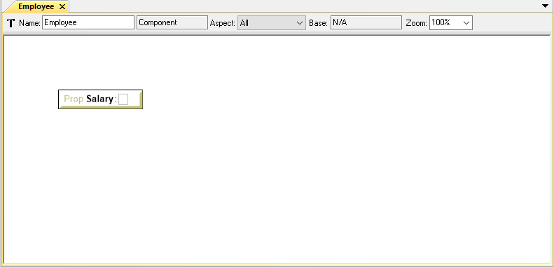
Double-click the Employee Component to open it.
From the Parts Browser pane on the left of the window drag a Property onto the open canvas.
Rename the property Salary. Do not set a value for Salary – its value will differ for each employee.
Double-click the Allen Component to open it. Notice that a Salary Property was automatically created.
Set the value of Allen’s Salary to 50000.
Inheritance can extend to several levels of depth. Let’s say that, within our company, we also have programmers. For programmers, we want to know their primary computer programming language. This property wouldn’t make sense for non-programmer employees, so we need a special class for them.
Right-click on Employee and choose .
Right-click on the TeamMembersInheritance folder and choose .
You will see a new Employee Component which includes a small “s” next to its icon.
Rename this Component to Programmer.
Double-click the Programmer Component to open it.
From the Parts Browser pane on the left of the window drag a Property onto the open canvas.
Rename the property to Language. Do not set a value for Language.
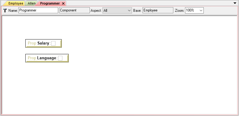
Now we have a special Programmer class of Component. It contains all of the Properties of Employee, as well as additional fields that apply only to programmers.
Right-click on Programmer and choose .
Right-click on the TeamMembersInheritance folder and choose .
You will see a new Programmer Component which includes a small “s” next to its icon.
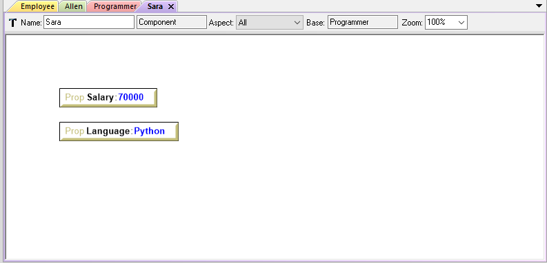
Rename this Component to Sara.
Double-click the Sara Component to open it.
Set the value of Sara’s Langauge to Python.
Set the value of Sara’s Salary to 70000.
In the case of a small project, it may be expedient to simply create each component from scratch; but as the scale of a project grows, these techniques become indispensable.
Components Library
Browsing Your Component Library
You can access the components in your project by using the GME Browser (on
the right hand side of the screen).
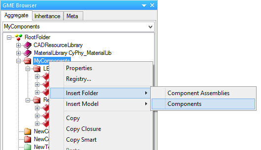
In the GME Browser, Components are contained in red Components Folders,
 . Component Folders can be nested and used for organization.
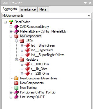
Example of Components in an OpenMETA Project
To create a new folder, right-click on the parent folder, and choose .
To move a component from one folder to another, just drag-and-drop it to the new folder.
Getting Components
To build designs in OpenMETA, you’ll need to have the necessary OpenMETA Components in your project. Components can be built from scratch, but they can also be imported.
Component packages are .zip files that include everything needed to use a
component in design and simulation, such as 3D CAD models, EAGLE schematics, and
icons. In this format, components can be exchanged freely between users or
downloaded from websites.
If you are interested in electronics design, you can clone the morph-components repository for a large library of electronics components.
Importing Components
Components can be shared in two forms, either as an .acm file with some
other files and folders around it, or as a .zip package that includes all
the file dependencies within it.
To import a Component:
Click the Component Importer,
 .
.If you are importing a…
a. Component
.acmfile, navigate to and select the .acm file. The importer will find the other files that this component depends on and import them into your project’s backend folders.b. Component
.zippackage, navigate to and select the .zip file. The ZIP file includes all of the files needed to use the component, and they’ll be copied into your project’s backend folders.
After the component is imported, the GME Console will display a link to the component as well as its path within the Components Folder tree of your OpenMETA project.
This process can be repeated for any components you feel will be necessary for your design. You can import multiple components at the same time by selecting all of them.
Exporting Components
OpenMETA includes a utility which will create component packages from the components in your OpenMETA project. These packages are .zip files which contain everything that’s needed to use a component.
To export a single component:
- Open the component by double-clicking on it in the GME Browser.
- Click the Component Exporter button,
 .
. - You’ll be prompted for a location in which to save the component package
.zipfile. - A component package ZIP file will be produced in the folder you selected.
To export all of the components in your OpenMETA project:
- Close all of your editing windows.
- Click the Component Exporter button, .
- You’ll be prompted for a location in which to save your component package
.zipfiles. - For each component in your OpenMETA project, a component package ZIP file will be produced in the folder you selected.