Building the Test Bench
TestBenches can be as simple as a few blocks for computation, or complex as many references that send and recieve data from different programs to compute large scale behavioral studies. The generic FEA TestBench consists of:
- Tool Features
- System Under Test
- Test Injection Points
Tip
If you wish to start the tutorial here, open the FEA_tutorial_part2.xme.
Tool Features
Before we can start building the TestBench, we have to give it a home folder.
- Right-click on the Root folder and choose .
- Right-click on the new Testing folder and choose .
- Rename this Simple_Cube_FEA.
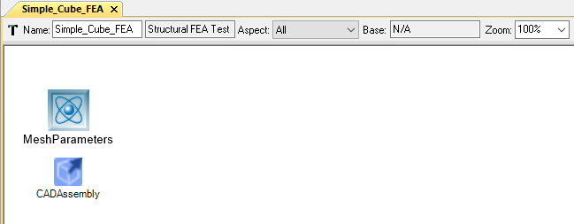
- Double-left-click Simple_Cube_FEA to open the blank TestBench canvas.
Next, we’ll add a Mesh Parameters object which allows us to specify to Patran, the meshing software, how we want to generate the mesh.
- In the Part Browser, locate Mesh Parameters and drag it into the workspace.
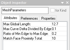
- Select the Mesh Parameters and change the values in the Attributes tab of the Object Inspector as shown below.
Now we’ll add a Workflow which tells our tool what task(s) it needs to execute to properly run our FEA TestBench.
- In the GME Browser Right-click on Testing and choose .
- Right-click on the new Workflow Definitions folder and choose .
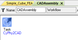
- Rename this Workflow CADAssembly.
- Right-click on the new CADAssembly workflow and choose .
- Redirect back to Simple_Cube_FEA, locate the WorkflowRef in the Part Browser and drag it into the workspace.
- Left-click the CADAssembly workflow and drop it on top of the WorkflowRef.
- Rename the ‘WorkflowRef’ CADAssembly.
System Under Test
A SystemUnderTest part tells the tool what we are trying to analyze in the TestBench. This acts much like a reference to our Cube_Assembly Component Assembly, which is in turn a reference to our Simple_Cube Component.
- In the Part Browser, locate the object System Under Test and drag it into the workspace.
- In the GME Browser, left click the Cube_Assembly and drop it on top of the System Under Test.
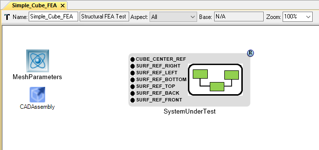
Note
There must be a blue circle with an R inside in the top right corner of the SystemUnderTest object indicating that this is a reference to the Component Assembly.
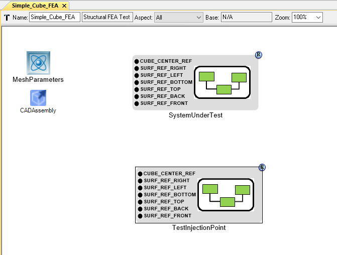
We have now told the tool what to analyze, but we haven’t specified how to do so yet. To do that we’ll add a TestInjectionPoint.
Test Injection Point
We will now specify what is happening to the CAD model we have referenced and where these actions are taking place on the model. For our FEA analysis we care greatly about how the part reacts when loaded under certain conditions. For simplicity, the Cube will be fixed at its base, while having a downward load applied to the top. (Imagine this as placing a large book over the entire top surface of a table and analyzing how the table responds to the newly applied load.) Intuitively, we know it is most fitting to treat this as a pressure (Weight of book / Area of cube).
- Locate the TestInjectionPoint in the Part Browser and drag it into the workspace.
- Left-click Cube_Assembly and drop it on top of the TestInjectionPoint.
Note
If the Surface_reference_points are not fully displaying their names, change the Port Label Length in the preferences tab of the object inspector to 0.
- In the Part Browser locate the Face object and drag it into the workspace. Change the Face Icon name in the Preferences tab of the Object Inspector to Surface.png.
- Double left-click the face to edit it. Inside, drop a ReferencePoint
- Direct back to Simple_Cube_FEA. Copy this edited Face and paste 1 more (for the bottom and top faces of the cube).
- Rename the faces Face_Ref_Top and Face_Ref_Bottom.
- Connect these faces to SURF_REF_TOP and SURF_REF_BOTTOM.
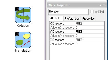
- In the Part Browser locate the DisplacementConstraint object and drag it into the workspace.
- Double left-click the DisplacementConstraint to edit it. Add in a Rotation and Translation part.
- Select the Rotation part, and in the Attributes tab of the`Object Inspector` change the X,Y,Z directions from Scalar to Free.
- Direct back to the Simple_Cube_FEA and connect the DisplacementConstraint to Face_Ref_Bottom.
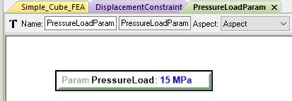
- In the Part Browser, drag and drop the PressureLoadParam into the workspace.
- Double left-click the PressureLoadParam and add in a PressureLoad.
- In the ‘Object Inspector’ set the
valueto 15. - To assign proper units: in the GME Browser, left-click the plus box next to . Locate Megapascal and drop it on top of the PressureLoad.
- Copy (Ctrl+C) the Pressure load and paste it inside of Simple_Cube_FEA.
- Connect this to the PressureLoadParam.
- Connect the PressureLoadParam to the Face_Ref_Top.
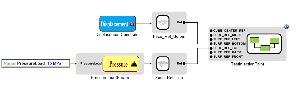
We have now specified that we want to place a 15MPa pressure over the entire top surface of the cube while keeping the entire bottom surface from translating in any direction. Next we must specify how we want to solve this problem and what data we want to solve for.
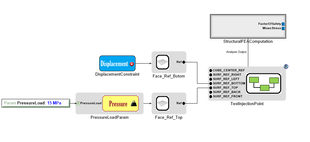
- Left-click on a blank space in the canvas; in the Object Inspector change the Solver Type to PATRAN_NASTRAN and the ElementType to Plate4.
- In the Part Browser add a StructuralFEAComputation. Double left-click to edit the part.
- Add in a FactorOfSaftey and MisesStress aspect, then redirect back to Simple_Cube_FEA.
- Connect the TestInjectionPoint to the StructuralFEAComputation by left-clicking on the box borders of both.
- In the Part Browser add two (2) Metric parts. Rename these FactorOfSaftey and MisesStress.
- Connect these to their StructuralFEAComputation counterparts.
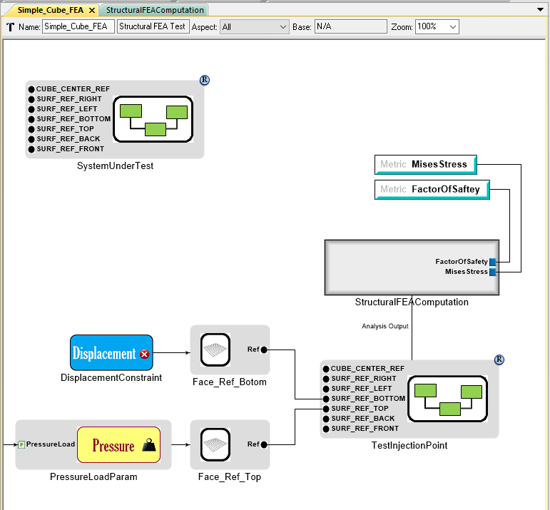
When conducting an FEA TestBench, we are generally interested in simulating a load and seeing the reaction of a part. In our case, we only want to see values that do not exceed the ultimate strength of the Cube. We can set this as a Metric Constraint that limits values to always exceed a factor of safety of 1.0.
- In the Part Browser locate Metric Constraint and drag it onto the canvas.
- Rename this ReserveFactorRequirement.
- Set the TargetValue to 1.0.
- Connect this to the FactorOfSaftey metric.
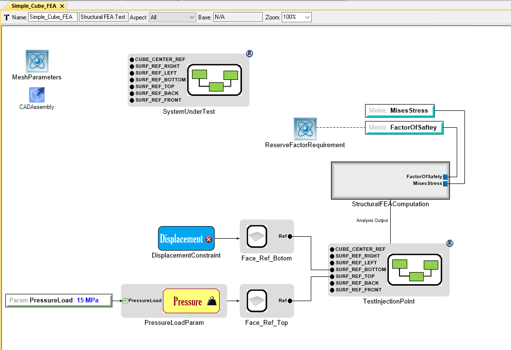
This constraint does not change how the user views the data but how the TestBench Manifest sorts data. This is generally good practice as it will help debug a design space if parts continually fail the factor of saftey requirement. Our now complete TestBench should look like this: