Generating a Schematic
The OpenMETA tools support the generation of schematics and layouts for EAGLE. For this type of analysis we will use the PlaceAndRoute_1x2 test bench, which generates manufacture-ready files of our component assembly for a 20mm x 40mm printed circuit board.
Configuring a Test Bench
- In your GME Browser, expand the folders.
- Locate the PlaceAndRoute_1x2 test bench.
- Double-click it to open it.
- Create a reference of SimpleLEDCircuit in the Test Bench by copying and pasting as a reference using the same method introduced in the Populate the Component Assembly section.
- Select the Reference role type: TopLevelSystemUnderTest.
Note
The procedure described in steps 4 and 5 is the same for referencing a design within any OpenMETA Test Bench.
Running a Test Bench
A test bench is executed by running the Master Interpreter. You can find its icon on the GME Toolbar:
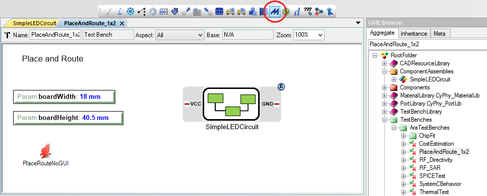
- Click the Master Interpreter icon.
- Make sure Post to META Job Manager is checked.
- Click OK.
- Once your job successfully completes and turns green in the Active Jobs tab of the Results Browser, right-click it and select Show in explorer.
In the folder, you will find a number of different files. One of them is the generated Eagle schematic: schema.sch. Double-click it and open it with Eagle.
Note
If this is your first time using Eagle, a dialogue box might ask how you want to run Eagle without a license. Click run as Freeware.
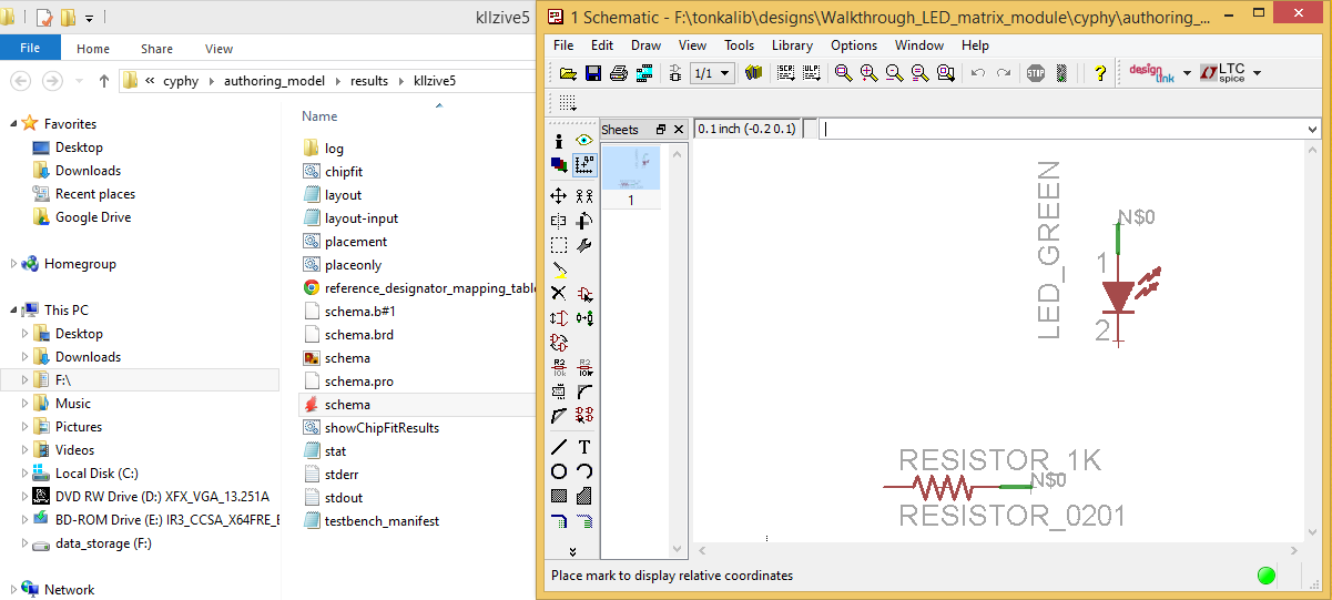
You’ll see the green LED and 1k resistor that we selected. You may also notice that the two parts are not connected with lines, but instead with nets. Generated schematics will not include lines, but will instead use nets like this that identify any number of pins that are connected together.
If your job does not execute properly, send us a note at support@metamorphsoftware.com.