Building a Basic LED Circuit Model
In this first section, we’ll build a simple LED circuit. Engineers often use multiple types of analysis software to test their designs. This practice takes time; you need to learn each piece of software and compose a model for each one that will test for a parameter. The OpenMETA tools, however, allow you to run multiple types of analyses by composing just one model.
Creating a New Component Assembly
In the OpenMETA tools, we build a design by instantiating components and joining their interfaces, yielding a Component Assembly. We call this process composition. From this composed design, we can generate new models and run analyses.
We begin by connecting our components in a single component assembly. Let’s set up our Component Assembly by making a new folder and model.
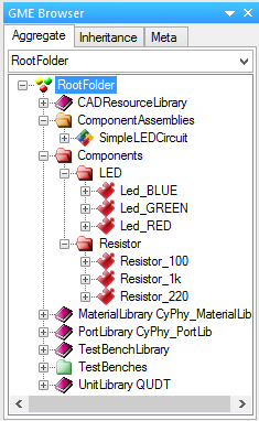
In the GME Browser window:
- Right-click on the RootFolder, and choose Insert Folder –> Component Assemblies.
- Right-click on ComponentAssemblies, and choose Insert Model –> Component Assembly.
- Rename this new component assembly SimpleLEDCircuit.
Browsing the Component Library
In the GME Browser window:
- Expand the RootFolder to see the folders in your project.
- Expand the Components folder, as well as its subfolders (LED and Resistor), to see the available components.
We have included six components into your project file: three resistors and three LEDs.
Populate the Component Assembly
Double-clicking on SimpleLEDCircuit will open a white canvas.
To populate a component assembly, the components need to be copied and pasted into the canvas as references. There are two ways to do this. We will show you the two different methods as we instantiate the LED and Resistor components.
Instantiate an LED using Method 1:
- In your GME Browser, locate Led_GREEN in the Components folder.
- Right-click on it and choose Copy.
- Right-click on your white canvas, and choose Paste Special –> As Reference.
Instantiate a resistor using Method 2:
- In your GME Browser, locate Resistor_1k.
- Drag and drop the resistor onto your white canvas with a right-click.
- Select Create Reference.
Warning
Do not drag with left-click as this will remove the component from
its containing folder and void any references that point to this component.
Undo this with (Control-z) or by selecting “” from the menu.
In the future, you can use whichever method you prefer, since they produce the same result.
Joining the Component Interfaces
The flow of current in this simple design will be as follows: . Since we don’t have a power source or ground connection yet, we’ll start by joining the .
- Change your cursor to Connect Mode by pressing
(Control-2)or clicking the Connect Mode button in the toolbar.
 - Click the icon next to P2 of the Resistor.
- Click the icon next to Anode of the LED.
If something goes wrong, you can backtrack with “undo” (Control-Z) or
. If you need to remove connections use
Disconnect Mode: (Control-3) or
 .
.
When you are done, return to Edit Mode: (Control-1) or
 .
.
Creating External Interfaces
Our circuit is still missing a power source and sink. We must create two external connectors into our circuit: power supply and electrical ground.
Create new external connectors for your component assembly
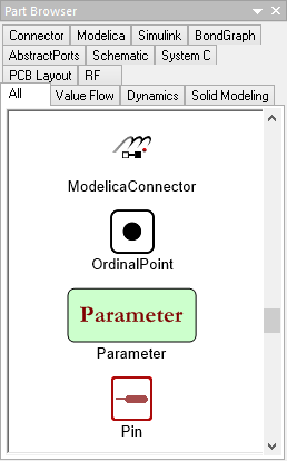
- In the Part Browser window on the left side, locate the Pin (see the figure below).
- Drag and Drop two Pins into your component assembly with left-click.
- Rename the pins to VCC and GND.
Connect external connectors to components
Recall the circuit architecture that we have planned: . We’ll use the same method as connecting the ports of two components.
- Return your cursor to Connect Mode (see above).
- Create a connection from VCC to P1 of the Resistor.
- Create a connection from GND to Cath of the LED.
Although we’re counting on the power and electrical ground to be provided externally, we’ve implemented the architecture we proposed at the beginning of the section: . Your component assembly should look like the figure below.
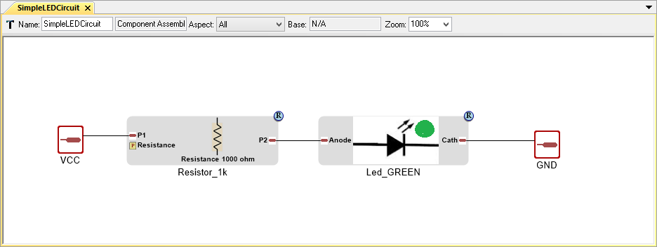
Completed LED and Resistor Assembly