Working with CAD Models
This section briefly describes the process for adding CAD resources to OpenMETA Components and generating CAD assemblies by integrating a number of OpenMETA Components into an OpenMETA Component Assembly and launching Metalink.
OpenMETA currently has a single publicly-available CAD integration: PTC Creo Parametric 3.0. For this reason, the below concepts will be explained using Creo.
Constraint Methodology
Key connection points on CAD resources are marked with named datums, which can be constrained in OpenMETA to the datums of other connected components to generate an assembly. By expressing these constraints in OpenMETA on these connection points, instead of relative-position offsets, a complex component can be automatically composed out of other simpler components using fixed and/or partially constrained joints.
Preparing CAD Files
Each part that is used in an OpenMETA project first needs to be prepared in the native CAD environment. Datums that will be used for constraints as well as any Parameters that will be used to adjust the dimensions of the part in OpenMETA need to be added at this time.
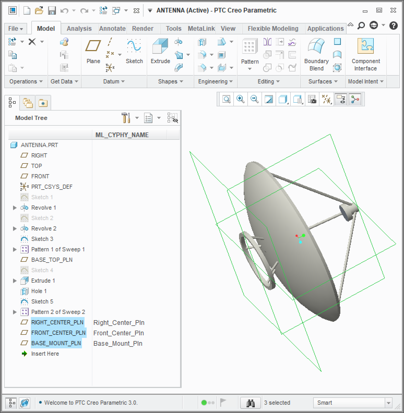
Antenna part with three datum planes to define a mounting interface
In the Antenna CAD part above, you can see three planes at the base of the antenna that will be used to constrain it to another component in a larger assembly.
Component Authoring Tool
The Component Authoring Tool (CAT) makes it easy to add a CAD resource to
an OpenMETA component by simply selecting the native part or assembly file
that you want added to the component.
To use the CAT, open the OpenMETA component for which you wish to add a
CAD resource and click the  button on the toolbar.
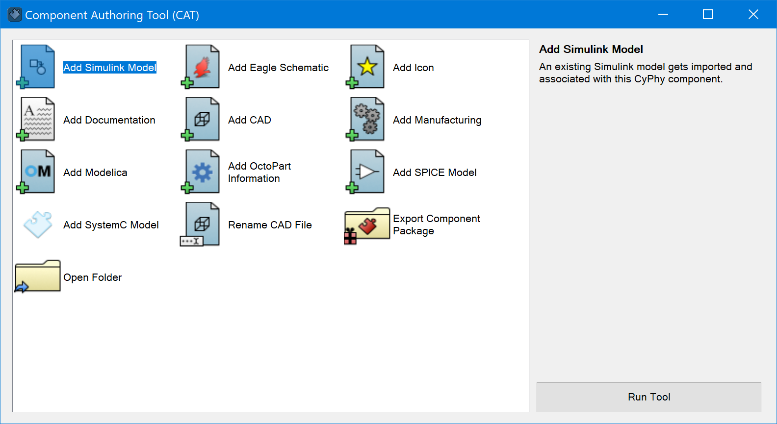
The CAT can be used to add many different types of domain models to an OpenMETA component, but to add a CAD resource, simply double-click the “Add CAD” icon. The next section describes the artifacts generated by the CAT.
CAD Models
The most important artifact generated by the CAT is a CAD Model model. This model contains references to any datums (planes, axis, coordinate systems, and points) that are defined in the geometry. A CAD Model model can also contain parameters, which are used to pass values from OpenMETA into the CAD tool. In the CAD tool these are often used as inputs to formulas or to dimension geometry.
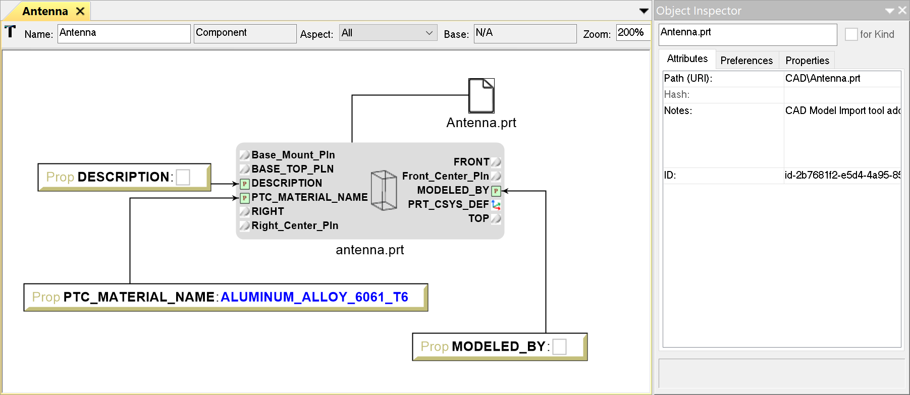
CAD Model created from the Antenna.prt CAD file
Each OpenMETA component has a corresponding folder in the components/
folder in the project directory;
this is where any domain specific files are stored.
The Resource atom that is connected to the CAD Model specifies
the location of the referenced native CAD file relative to the component
directory.
For the Antenna component shown above, the referenced native CAD file
can be found at CAD/Antenna.prt relative to the component base folder.
Note
Creo versions its files by appending a numerical extension,
but it only considers the latest; e.g. if you have both a
CAD/Antenna.prt and a CAD/Antenna.prt.1 file in your component
folder, only the latter will be used by Creo.
Any unneeded atoms in the CAD Model can be removed for readability. Additionally, CAD Models and Resources can be added to a component manually, but we recommend using the CAT as this becomes rather tedious when there are many CAD files that need to be added.
Connectors
OpenMETA Connectors allow us to wrap multiple domain ports into a single exposed connector on an OpenMETA Component. For CAD purposes we often wrap a collection of datums that represent an interface into a single connector.
Below you can see the three planes of the antenna part being wrapped by a single “Cargo_To_Antenna” connector.
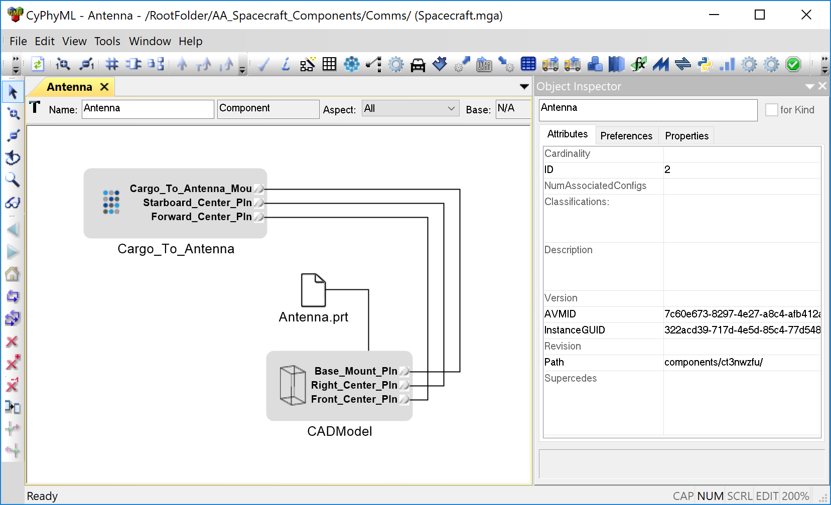
Antenna component with an OpenMETA Connector
See the Connectors section of the Components chapter for more information on Connectors.
Composing Assemblies
Composing CAD assemblies in OpenMETA is as simple as adding components to an OpenMETA Component Assembly and creating a connection between the desired connectors.
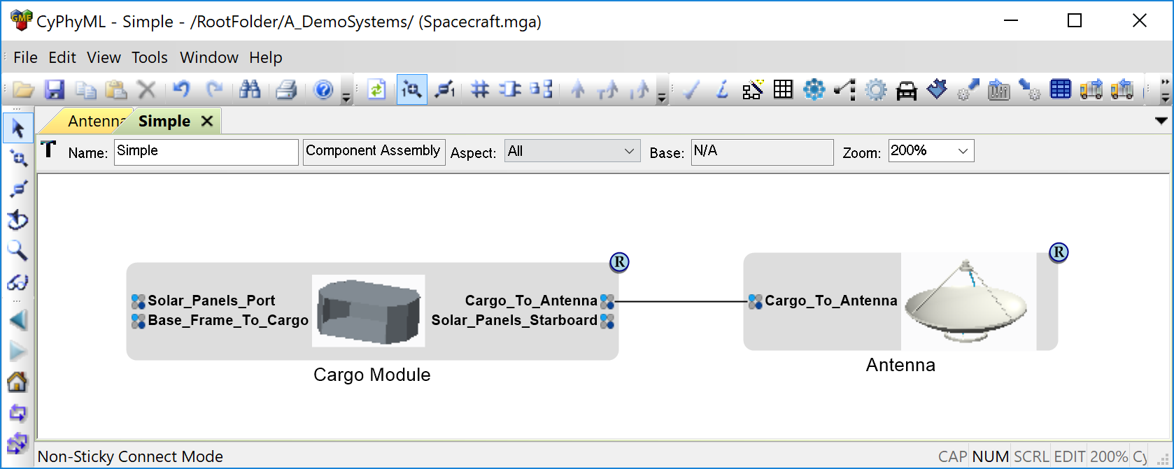
Simple OpenMETA Assembly
After an assembly is created, you can view the composed CAD geometry by executing a CAD Test Bench or running Metalink. Visit the CAD Test Benches section to see how to properly set up and execute a CAD Test Bench. The Metalink tool is described in the next section.
Examples
With Creo installed, check out the Spacecraft Model walkthrough.
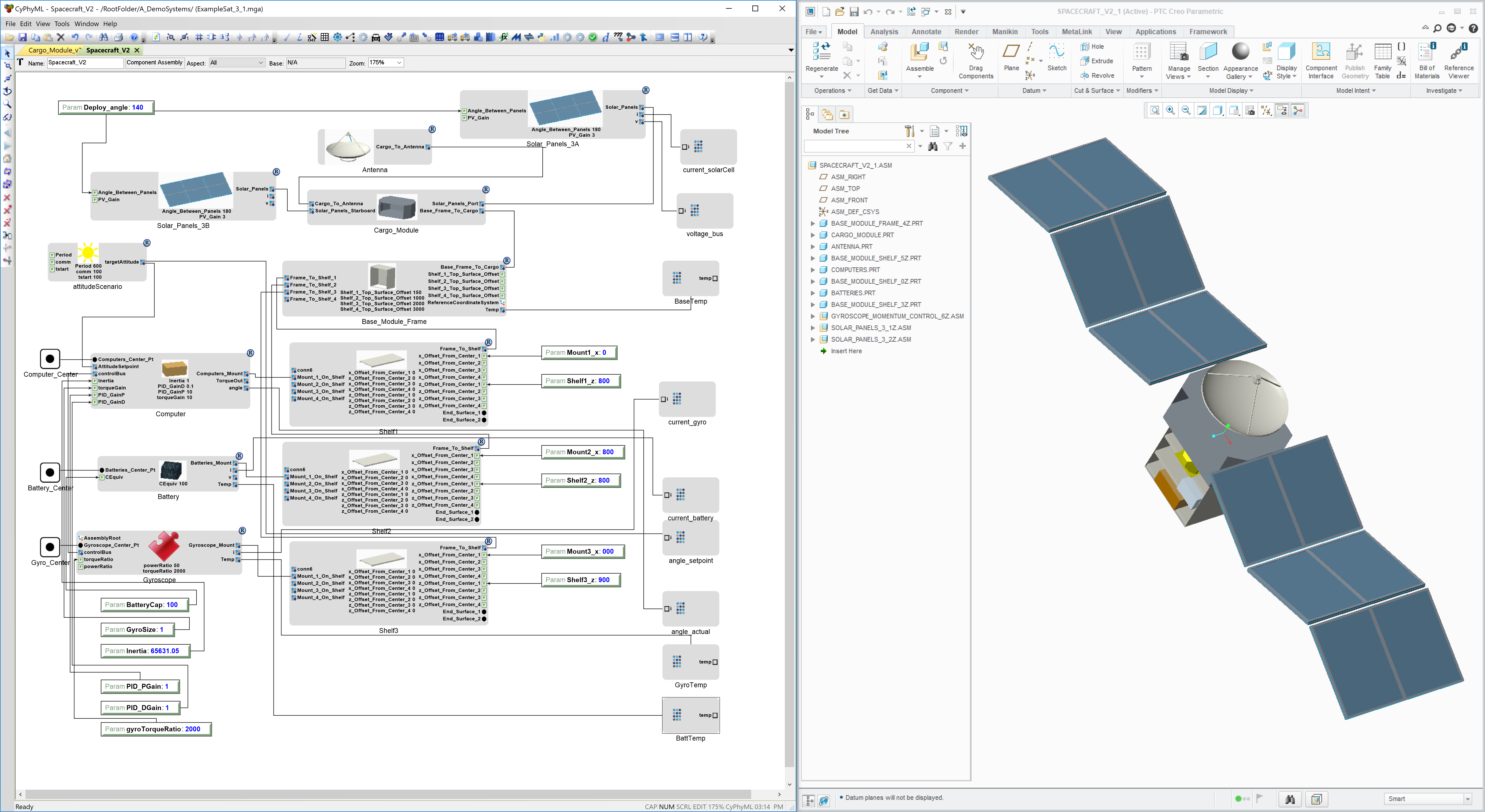
Image of the Spacecraft Component Assembly and CAD Representation