The guides in this section detail the model interpreters provided with the META tools.
This section is oriented towards test bench authors, for whom deep technical details will be valuable. This is as opposed to end-users, who will primarily be consumers of test benches, and should not need to know the technical details of interpreters.

CyPhy2Schematic generates circuit models. It has several modes which support a number of capabilities, including:
NOTE: Values of type Boolean are considered false if they are unspecified or null. Any other value is considered true.
| Key | Value Type | Description |
|---|---|---|
| doSpice | Boolean | If true, generate a SPICE simulation model. Ignore all other parameters. If false, produce an EAGLE schematic model. |
| doChipFit | Boolean | Run an analysis that determines whether the given components will fit into the given dimensions. This mode requires the TestBench to have 2 Parameters, and produces 2 Metrics. For more details, read the ChipFit Mode section below. |
| showChipFitVisualizer | Boolean | If true, a 2D viewer will be launched for the ChipFit results as part of test bench execution. Execution will be blocked until the window is closed. |
| doPlaceOnly | Boolean | Generates a layout for the PCB and saves it as an EAGLE board file |
| doPlaceRoute | Boolean | Same as doPlaceOnly, but also uses EAGLE's auto-router to route the signals on the board |
| skipGUI | Boolean | If true, don't display a GUI to the user when the interpreter runs as part of a workflow, even on the first run over a design space. |
If doSpice is not true, then the interpreter operates in EDA mode. In this mode, it will produce an EAGLE schematic model from the CyPhy model. Depending on the other options selected, it can also do a ChipFit analysis, auto-placement of components on the PCB, and auto-routing of the traces on the PCB.
| Filename | Artifact Tag | Description |
|---|---|---|
layout-input.json | none | Input to the ChipFit and Placement tools. Provides board size and layer count constraints. For each package in the design, provides name, width, and height (in millimeters). |
schema.sch | none | The generated EAGLE model |
chipfit.bat | none | Runs the ChipFit analysis |
placeonly.bat | none | Generates a board layout from layout-input.json and synthesizes an EAGLE board file as schema.brd |
placement.bat | none | Same as placeonly.bat, but also uses EAGLE to auto-route the signals on the board. |
reference_designator_mapping_table.html | none | Provides mapping from the auto-generated reference designators in the EAGLE model to the paths of components from the original CyPhy project. |
This mode supports the following TestBench Parameters.
| Parameter Name | Value Type | Description | Required |
|---|---|---|---|
| boardWidth | real number | The width (in millimeters) of the area available for components. | Required |
| boardHeight | real number | The height (in millimeters) of the area available for components. | Required |
| boardTemplate | string | The relative (to the project) path of a PCB board template file | Optional |
| designRules | string | The relative (to the project) path of a design rule file that specifies place and route guidelines for PCB | Optional |
| autorouterConfig | string | The relative (to the project) path of an EAGLE autorouter settings file to be used by the autorouter | Optional |
| boardEdgeSpace | string | The minimum distance (in millimeters) between the boundary of a component and the edge of the board | Optional |
| interChipSpace | string | The minimum distance (in millimeters) between the boundaries of adjacent components | Optional |
If the doChipFit value is true, then the ChipFit Mode will be activated. In this mode, the test bench will run an analysis that determines whether the given components will fit into the given dimensions.
This mode produces two Metrics. If these metrics aren't provided in the TestBench, they will be added into testbench_manifest.json after ChipFit execution.
Note: In the Metric names that follow, (x) and (y) are replaced by the boardWidth and boardHeight, respectively, as defined above.
| Metric Name | Value Type | Description |
|---|---|---|
| fits_(x)_by_(y) | true/false | Whether the components in the design will fit within the given space |
| pct_occupied_(x)_by_(y) | float | The percentage of the available space occupied by the given components. |
The SPICE Mode will generate and run an NGSPICE-compatible SPICE model.
| Filename | Artifact Tag | Description |
|---|---|---|
runspice.bat | none | Runs the SPICE simulation |
schema.cir | none | The generated SPICE model |
siginfo.json | none | Provides mappings from SPICE signals to ports in the CyPhy model |

CyPhy2SystemC generates and executes behavioral test benches using a SystemC discrete event simulator. The interpreter includes the standard SystemC v2.3.1 library from the Accellera Systems Initiative and the core components of the ARA ecosystem. The interpreter targets Visual Studio 2010 (C++) with no additional/external dependencies.
The interpreter needs to be executed from a proper testbench with at least one component/susbsytem under test and one or more test components. A successful execution involves the following steps:
test_main.cpp) is generated, which instantiates and wires all components and starts the SystemC simulation. Trace statements are also added for top-level signalsSystemCTestBench) which includes the SystemC simulator library and the essential ARA componentsResource to the component in the CyPhy model)SystemCTestBench.vcd) and its exit status reflects the number of failed testsNOTE: The current version does not require nor handle any special workflow parameters.
This interpreter supports the following Parameters.
| Parameter Name | Value Type | Units | Description |
|---|---|---|---|
| simulationTime | real number | Time | The (maximum) length of the simulation time |
This interpreter generates a new folder for the Visual Studio Solution with subfolders containing the SystemC library and essential ARA components.
| Directory/File Path | Artifact Tag | Description |
|---|---|---|
SystemCTestBench.sln | none | Visual Studio solution file |
SystemCTestBench.vcxproj | none | Visual Studio C++ project |
SystemCTestBench.vcxproj.filters | none | Visual Studio source file folder definitions |
include/* | none | Include files for the SystemC and ARA libraries |
libD/* | none | Debug builds of the SystemC and ARA libraries |
libR/* | none | Release builds of the SystemC and ARA libraries |
test_main.cpp | none | Generated top-level SystemC source file (instantiation and wiring) |
<other>.cpp/.h/ .ino | none | Copies of referenced SystemC sources in third party components and Arduino firmware sources |
The execution of the generated test bench generates the following output file(s):
| Directory/File Path | Artifact Tag | Description |
|---|---|---|
SystemCTestBench.vcd | none | VCD (Value Change Dump) signal traces |

The CyPhy2RF interpreter builds up the EM simulation model of the Ara module, generates the input files for OpenEMS and executes the simulator. It imports and generates the models described with CSXCAD XML scheme of OpenEMS.
The interpreter needs to be executed from a proper testbench with one System Under Test and one Excitation test component. Upon successful execution the interpreter:
NOTE: The current version assumes that OpenEMS is installed under the C:\OpenEMS\ directory.
The current version does not require nor handle any special workflow parameters.
This interpreter supports the following parameters:
| Parameter Name | Value Type | Units | Description |
|---|---|---|---|
| Frequency | real number | Hz | The center frequency of the excitation signal |
| Resolution | real number | mm | The target resolution in the Ara Endo vicinity |
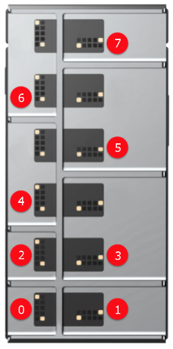
| Slot | positive integer | - | The Ara Endo slot index to be used (see the figure below) |
| Directory/File Path | Artifact Tag | Description |
|---|---|---|
run_dir_simulation.cmd | - | Batch file that runs the OpenEMS simulation and postprocessing |
openEMS_input.xml | - | Simulation description for the OpenEMS simulation |
nf2ff_input.xml | - | Simulation description for the postprocessing steps |
| Directory/File Path | Artifact Tag | Description |
|---|---|---|
run_sar_simulation.cmd | - | Batch file that runs the OpenEMS simulation and postprocessing |
openEMS_input.xml | - | Simulation description for the OpenEMS simulation |
nf2ff_input.xml | - | Simulation description for the postprocessing steps |
The execution of the SAR postprocessing generates the following output files:
| Directory/File Path | Artifact Tag | Description |
|---|---|---|
SAR-X.png | CyPhy2RF:SAR:X | PNG image with the Y-Z plane cross-sectional cut of the head phantom at the SAR maximum location |
SAR-Y.png | CyPhy2RF:SAR:Y | PNG image with the X-Z plane cross-sectional cut of the head phantom at the SAR maximum location |
SAR-Z.png | CyPhy2RF:SAR:Z | PNG image with the X-Y plane cross-sectional cut of the head phantom at the SAR maximum location |
The CyPhy2CADPCB interpreter allows a user to visualize their model in 3-D by generating either a STEP or STL file based on the layout.JSON file that is created with the CyPhy2Schematic interpreter. The layout.JSON file describes the location of components on a PCB as calculated by EAGLE. However, the origin of components in the EAGLE simulation and the origin in the CAD model may not be the same. This interpreter traverses the model searching for components that have associated CADModels. If a component also has an EDAModel connected to the CADModel, the CAD2EDATransform connection defines the transform needed to align the EDAModel and CADModel's coordinate systems. If a component contains an EDA model and no CAD model, a placeholder cube will be created in the final assembly, with the component length/width dimensions at the coordinates specified in the layout.JSON. Any components without an EDA model are excluded from the final assembly.
The assembly STEP/STL file is generated using FreeCAD. At this time, only the assembly of STEP and STL files are supported. If a component has an EDAModel that has multiple CADModels of varying format associated with it, the interpreter gives preference to the model that matches the format specified in the visualizerType parameter. If the "mix" option is chosen, STEP files are given preference over STL. If multiple CADModels of the same format point to one EDAModel, one is chosen at random. AP203 and AP214 are considered the same format.
The layout.JSON input file that the assembly is based on can be specified in 4 ways:
layout.JSON.The interpreter needs to be executed from a proper testbench with one SystemUnderTest and a Workflow definition. Upon successful execution the interpreter:
layout.JSON file specified and copies it to the output directory.If you desire the layout file to be generated by first running the PlaceRoute testbench, the Workflow definition must contain two tasks: one for CyPhy2Schematic and the other for CyPhy2CADPCB. The tasks must be connected FROM CyPhy2Schematic TO CyPhy2CADPCB.
NOTE: If all parameters are left as null, the interpreter defaults to having the user select a layout.JSON via a file browser.
| Key | Value Type | Description |
|---|---|---|
| launchVisualizer | String | If true, once the assembly script has successfully run, a web visualizer will automatically launch and load the generated STEP file. Not yet implemented - value has no effect on simulation |
| layoutFilePath | String | If specified, assembly will be created based on this layout.JSON. |
| runLayout | String | If true, a CyPhy2Schematic testbench will first be created using the doPlaceRoute parameter setting prior to executing the assembly script. |
| useSavedLayout | String | If true, use a previously generated layout.JSON associated with the testbench's SystemUnderTest. This file should be stored in the project directory's "designs" folder within a subfolder named after the component assembly's design ID. |
| visualizerType | String | Specifies the format of the CADModels to be assembled. Supported types include STEP (all STEP models), STL (all STL models), or MIX (a mixture of STEP/STL). If parameter is left as null, the program defaults to "STEP". |
No parameters are used in the CyPhy2CADPCB interpreter. However, if the interpreter is executed with runLayout set to true, the following parameters are supported for the PlaceAndRoute analysis:
| Parameter Name | Value Type | Description | Required |
|---|---|---|---|
| boardWidth | real number | The width (in millimeters) of the area available for components. | Required |
| boardHeight | real number | The height (in millimeters) of the area available for components. | Required |
| Directory/File Path | Artifact Tag | Description |
|---|---|---|
CT.JSON | - | Component information file - specifies path to CAD model and associated CAD-to-EDA-model transforms. |
layout.JSON | - | File describing component locations on PCB as determined by EAGLE. |
BoardLayout.step (.stl) | - | STEP (STL) file of component assembly |
BoardLayout.FCStd | - | FreeCAD native format file of component assembly. |
NOTE: An assembly is able to be generated with a mixture of STEP and STL files. However, if any STL files are present, the format of the generated assembly will be STL. Due to this, the launchVisualizer workflow parameter will be disregarded.